Introduction to Proximity-Based Lighting Control
The integration of proximity sensors into fluorescent lighting control systems represents a significant advancement in building automation and energy management. This technology moves beyond simple manual switches or basic motion detectors, offering a more nuanced and efficient approach to illumination. Proximity sensors, typically utilizing infrared (IR), ultrasonic, or capacitive sensing principles, detect the presence or approach of an object—most commonly a person—within a defined field without physical contact. When applied to fluorescent lighting circuits, these sensors enable lights to activate only when an area is occupied and deactivate after a predetermined period of vacancy, leading to substantial reductions in energy consumption and extended lamp life.
Core Sensor Technologies and Selection Criteria
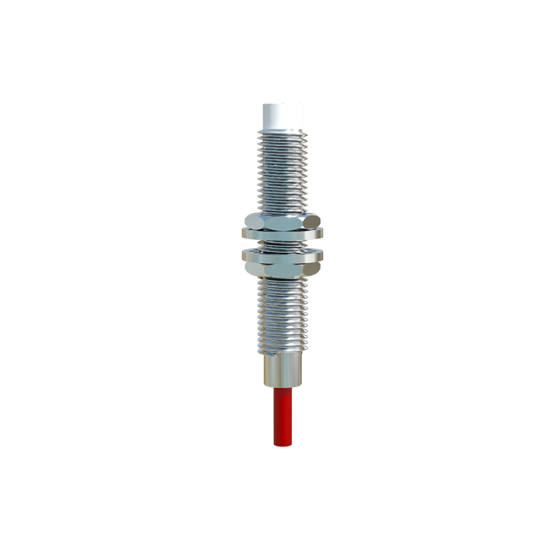
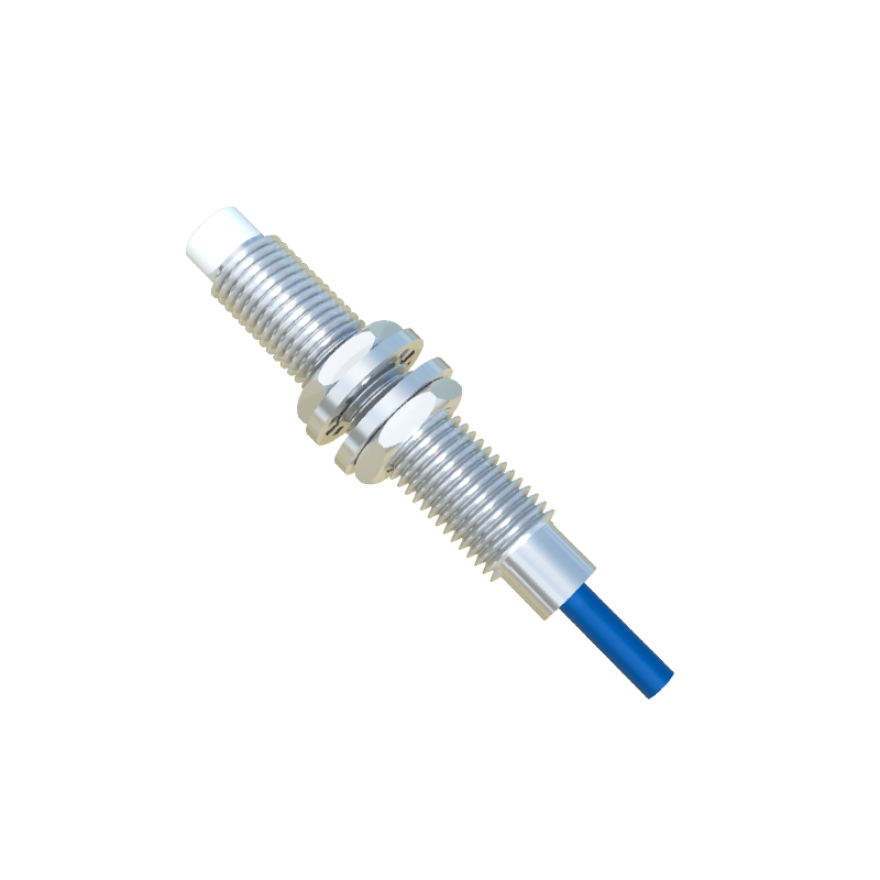
Selecting the appropriate proximity sensor is critical for system performance. Inductive proximity sensors are unsuitable for human detection in this context, as they sense metallic objects. For lighting control, passive infrared (PIR) sensors are the most prevalent. They detect changes in infrared radiation emitted by warm-bodied objects moving within their detection zones. Ultrasonic sensors emit high-frequency sound waves and measure the reflection time, detecting even minor movements, making them suitable for areas where occupants may be relatively stationary. Capacitive sensors can detect the presence of a person through non-metallic barriers but are less common in standard lighting applications. Key selection parameters include detection range, coverage pattern (wide-angle or directional), sensitivity adjustment, and immunity to environmental interference from HVAC drafts or sunlight.
System Architecture and Wiring Integration
Integrating a proximity sensor into a standard fluorescent lighting circuit involves interfacing the sensor's relay output with the lighting ballast's control lines. Modern systems often employ a low-voltage control scheme. The proximity sensor, powered by a 24VAC/DC source, acts as a switch for its internal relay. The relay's dry contacts are then wired in series with the switched line feeding the lighting ballasts or, more commonly, to the control input of an electronic ballast. For T8 or T5 fluorescent fixtures with programmable rapid-start or instant-start electronic ballasts, the sensor typically connects to the 0-10V DC dimming control wires or a dedicated digital control input (like DALI). This allows not only on/off control but also potential dimming based on occupancy or ambient light levels when paired with photocells.
Configuration and Calibration for Optimal Performance
Proper configuration is essential to avoid user annoyance and maximize savings. The primary settings are the delay time and the sensitivity or detection range. The delay time, adjustable from seconds to several minutes, determines how long the lights remain on after the last detected motion. A typical office setting may use a 10-15 minute delay. Sensitivity adjustment prevents false triggers from small pets or moving objects outside the target zone while ensuring reliable human detection. The sensor's field of view must be carefully aimed to cover the intended area without "seeing" adjacent corridors or outside windows, which could cause erratic switching. For large, open-plan areas, a network of sensors may be wired in parallel or using a master-slave configuration to ensure full coverage.
Energy Efficiency and Cost-Benefit Analysis
The primary driver for adopting proximity-controlled lighting is energy conservation. Fluorescent lights, while more efficient than incandescent, still consume significant power. By ensuring lights are off in unoccupied spaces, energy usage can be reduced by 20% to 50%, depending on occupancy patterns. This directly lowers electricity costs and demand charges. Furthermore, reducing the operating hours extends the lifespan of both the fluorescent tubes and the ballasts, decreasing maintenance and replacement costs. A simple payback period for a retrofit project can often be calculated within 2-4 years, considering the cost of sensors, installation labor, and the projected kWh savings at the local utility rate.
Challenges and Technical Considerations
Despite the benefits, several challenges exist. Sensor placement is paramount; a poorly located sensor can create "dark zones" or fail to detect stationary occupants. Compatibility with the existing ballast type must be verified. Some older magnetic ballasts may not interface cleanly with sensor relays, requiring ballast upgrades. In environments with high ceilings, sensors with sufficient range must be selected. Additionally, building codes and standards, such as ASHRAE 90.1 and IECC, mandate automatic lighting shut-off in many commercial spaces, making such systems not just economical but often a compliance requirement. Engineers must also consider fail-safe operation and potential integration with broader building management systems (BMS) for centralized monitoring and control.
Future Trends and Conclusion
The future of proximity-controlled lighting is converging with the Internet of Things (IoT) and LED technology. While this article focuses on fluorescent systems,