Understanding Proximity Sensor Dimensions
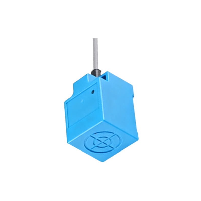
Proximity sensors are critical components in industrial automation, designed to detect the presence or absence of an object without physical contact. Their dimensions play a vital role in integration, affecting mounting, sensing range, and application suitability. A standard proximity sensor size chart typically includes key parameters such as body diameter, length, thread size, and sensing face dimensions. For cylindrical inductive sensors, common body diameters range from M4 (4mm) to M30 (30mm), with lengths varying from 40mm to 80mm depending on the model. Capacitive and ultrasonic sensors may have different form factors, often rectangular or square, with dimensions like 20mm x 40mm x 15mm. Understanding these measurements is essential for ensuring proper fit in confined spaces and alignment with target objects. Engineers must consult manufacturer datasheets for precise values, as even minor deviations can impact performance in high-precision tasks like robotic assembly or conveyor belt monitoring.
Key Parameters in Size Charts
A comprehensive proximity sensor size chart provides detailed specifications beyond basic dimensions. Key parameters include the sensing range, which correlates with sensor size—larger sensors often offer longer ranges, such as 15mm for an M18 model versus 5mm for an M8. Thread type and pitch (e.g., M12x1.0 or 1/2"-20 UNF) are crucial for mounting in international systems. The housing material, typically stainless steel or nickel-plated brass, influences durability and size tolerance under thermal expansion. Additionally, charts note the connector type (e.g., M8 or M12) and cable length, affecting overall footprint in control panels. For embedded applications, flush-mountable sensors have reduced protrusion dimensions, while non-flush versions require more space. By cross-referencing these parameters with operational needs—like temperature ranges up to 100°C or IP67 protection—users can avoid incompatibilities that lead to system downtime.
Interpreting Dimensional Diagrams
Dimensional diagrams in proximity sensor documentation use standardized symbols to convey critical measurements. These illustrations typically show front, side, and top views, with callouts for body length (L), width (W), and height (H). For cylindrical sensors, diagrams highlight thread length (Le) and overall installed length, including the sensing face. Tolerances, such as ±0.5mm, are marked to guide machining and alignment. In complex designs, like rectangular diffuse reflective sensors, diagrams may separate the emitter and receiver dimensions to clarify spacing requirements. Engineers should prioritize diagrams from reputable manufacturers like Omron, Sick, or Pepperl+Fuchs, as they adhere to ISO norms for accuracy. When interpreting, note any recesses or grooves that affect mounting depth, and verify clearance distances to adjacent metal surfaces to prevent electromagnetic interference in inductive models.
Selection Based on Size Constraints
Choosing the right proximity sensor involves balancing size with performance. In space-limited applications—such as packaging machinery or CNC tool changers—compact sensors like M5 or M8 cylinders are preferred, with sensing ranges up to 2mm. For longer ranges, larger M30 sensors can detect objects up to 40mm away but require ample mounting room. Consider the target object size: small parts need precise sensors with minimal dead zones, often achieved via reduced housing dimensions. Environmental factors also matter; high-vibration settings may necessitate robust, larger sensors with reinforced threads. Utilize online configurators or CAD models from suppliers to simulate fit in virtual layouts. Always verify the "effective sensing area" on charts, as it dictates alignment tolerance. For multi-sensor arrays, ensure spacing per diagrams to prevent crosstalk, especially in high-density automation cells.
Industry Applications and Size Trends
Proximity sensor sizes evolve with industry demands. In automotive manufacturing, miniaturized M3 sensors are gaining traction for tight engine compartment installations, while food processing favors large, hygienic M18 models with smooth surfaces for easy cleaning. Emerging trends include IO-Link-enabled sensors that integrate electronics into compact housings, reducing control cabinet space. Standardization bodies like IEC 60947-5-2 promote uniform sizing for interchangeability. In practice, engineers often maintain internal size charts comparing brands to streamline procurement. For retrofit projects, adaptor rings may address minor dimensional mismatches. As Industry 4.0 advances, sensors with embedded diagnostics are shrinking in size, enabling smarter, space-efficient factories. Regular updates to size charts are recommended, as manufacturers frequently release optimized designs for sectors like logistics and renewable energy.
Best Practices for Using Size Charts
To maximize accuracy, follow best practices when referencing proximity sensor size charts. First, download the