Understanding Proximity Sensor 12 Specifications
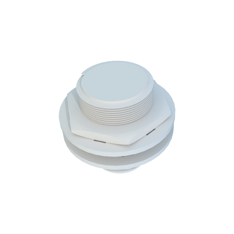
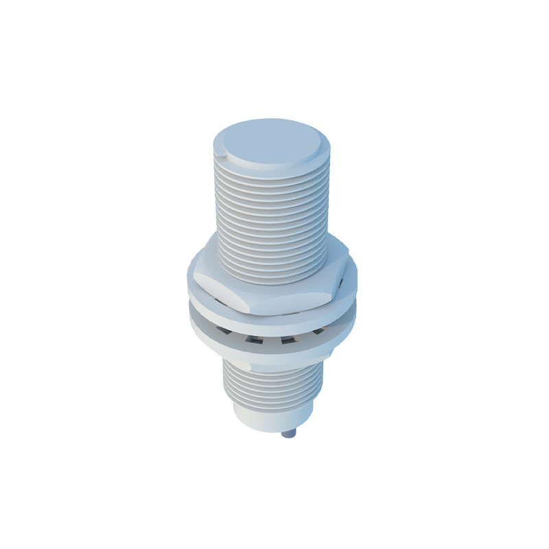
Proximity Sensor 12 is a widely used inductive sensor designed for industrial automation applications. Before proceeding with setup, it is crucial to review its technical specifications, including sensing range, output type (e.g., NPN or PNP), voltage requirements (typically 10-30V DC), and environmental ratings such as IP67 protection. Familiarizing yourself with these parameters ensures compatibility with your control system and prevents operational issues. Always refer to the manufacturer's datasheet for precise details, as variations may exist between models.
Pre-Installation Safety and Preparation
Safety is paramount when working with electrical components. Begin by disconnecting power to the circuit or machinery where the sensor will be installed. Verify the absence of voltage using a multimeter. Gather necessary tools, including screwdrivers, wire strippers, and appropriate cables. Ensure the mounting location is clean, free from debris, and within the sensor's specified temperature and humidity limits. Proper preparation minimizes risks and facilitates a smooth installation process.
Mounting and Alignment Procedures
Mount Proximity Sensor 12 securely using the provided brackets or hardware, ensuring it is positioned parallel to the target object. Maintain the recommended sensing distance—usually 2-4 mm for metallic objects—to avoid false triggers or reduced sensitivity. Avoid mounting near other electromagnetic sources, such as motors or transformers, to prevent interference. Tighten fasteners adequately but avoid over-torquing, which could damage the housing. Test alignment by moving the target object across the sensing face to confirm consistent detection.
Wiring and Electrical Connections
Connect the sensor wires according to the designated output type. For NPN (sinking) outputs, link the black wire to the load and brown wire to positive voltage; for PNP (sourcing) outputs, connect the black wire to the load and blue wire to ground. The brown wire typically receives positive DC voltage, while the blue wire is for ground. Use shielded cables in noisy environments to reduce electrical noise. Double-check connections against the wiring diagram to prevent short circuits or reverse polarity, which could permanently damage the sensor.
Configuring Sensitivity and Response Time
Many Proximity Sensor 12 models feature adjustable sensitivity via a potentiometer or DIP switches. Rotate the potentiometer clockwise to increase sensitivity for detecting smaller objects, or counterclockwise to decrease it and avoid interference from background materials. Set response time based on application speed; faster processes require shorter response times (e.g.,<1 ms). Avoid excessive sensitivity adjustments, as this may cause instability. Use an oscilloscope or PLC monitoring to fine-tune settings for optimal performance.
Testing and Calibration Steps
After installation, power on the system and observe the sensor's indicator LED. It should illuminate when a target object enters the sensing range. Use a multimeter to measure output voltage or current, ensuring it matches specifications (e.g., 24V DC output). Perform repeated tests with varying target sizes and positions to verify reliability. If the sensor fails to detect objects, recheck alignment, wiring, and sensitivity settings. Calibration may involve adjusting the potentiometer while testing with standard reference objects.
Troubleshooting Common Issues
Common problems include intermittent detection, false triggers, or no output. Start by inspecting wiring for loose connections or damage. Verify power supply stability, as voltage fluctuations can affect performance. Check for environmental factors like dust, moisture, or metal shavings obstructing the sensing face. If interference is suspected, relocate the sensor or install ferrite cores on cables. Consult the manufacturer's troubleshooting guide for error codes or LED blink patterns specific to Proximity Sensor 12.
Maintenance and Best Practices
Regular maintenance extends the sensor's lifespan. Periodically clean the sensing face with a soft cloth to remove contaminants. Inspect cables and connectors for wear, especially in high-vibration areas. Document settings and calibration records for future reference. Implement preventive measures, such as using surge protectors in circuits prone to voltage spikes. Train personnel on proper handling and setup protocols to ensure consistent operation. Proactive maintenance reduces downtime and enhances system efficiency.