Introduction to Proximity Switch Sensors and Solenoid Valves
Proximity switch sensors are non-contact devices widely used in industrial automation to detect the presence or absence of objects without physical contact. These sensors operate based on electromagnetic, capacitive, or inductive principles, generating an electrical signal when a target enters their sensing range. Solenoid valves, on the other hand, are electromechanical components that control fluid flow by converting electrical energy into mechanical motion. They are essential in applications such as pneumatic systems, hydraulic circuits, and process control. Integrating proximity sensors with solenoid valves enables precise, automated control, enhancing efficiency and reliability in manufacturing, packaging, and assembly lines. This synergy reduces manual intervention, minimizes wear, and improves safety by ensuring valves activate only when required conditions are met.
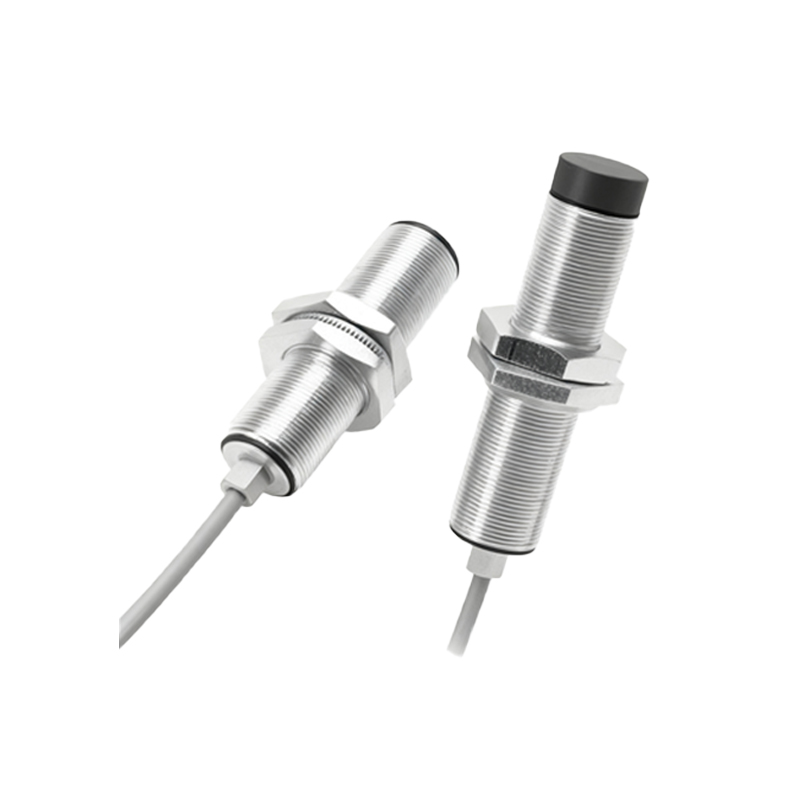
Working Principles of Proenoid Switch Sensors
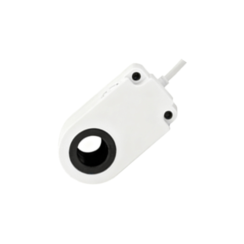
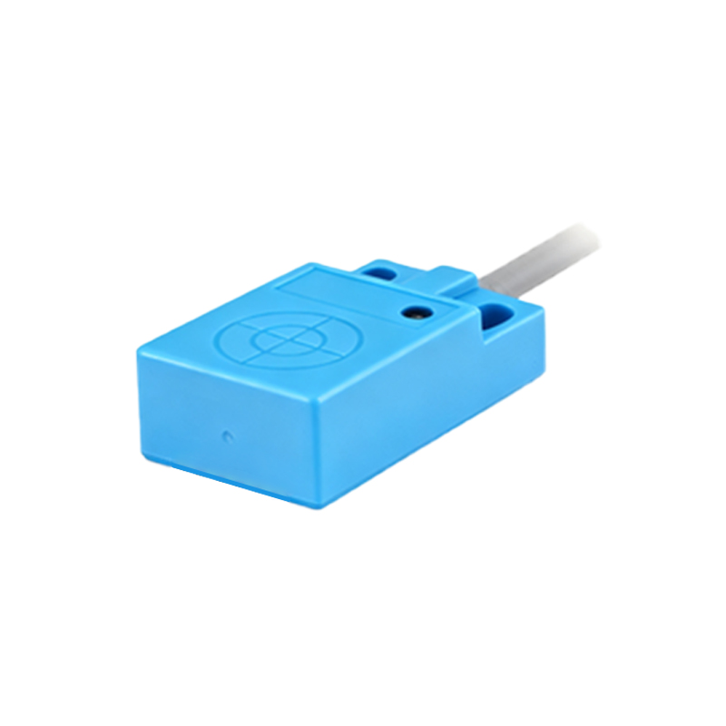
Proximity switch sensors function by emitting an electromagnetic field or beam. Inductive sensors detect metallic objects through changes in oscillation amplitude when a metal target approaches, while capacitive sensors respond to both metallic and non-metallic materials by measuring capacitance variations. Upon detection, the sensor's output switches from a normal state (e.g., open or closed) to an active state, sending a signal to a control unit like a PLC (Programmable Logic Controller). This signal triggers subsequent actions, such as energizing a solenoid valve. Key specifications include sensing distance, response time, and output type (e.g., NPN or PNP). For instance, in high-speed automation, fast-response sensors ensure timely valve actuation, preventing delays that could disrupt production cycles.
Control Mechanisms for Solenoid Valves
Solenoid valves consist of a coil, plunger, and valve body. When an electrical current flows through the coil, it creates a magnetic field that moves the plunger, opening or closing the valve orifice to regulate fluid flow. Control is typically managed via digital signals from sensors or PLCs. In a setup with a proximity sensor, the sensor's output connects to the valve's control circuit. For example, when the sensor detects a part on a conveyor, it sends a signal to the PLC, which then energizes the solenoid valve to release compressed air for actuating a cylinder. This closed-loop system allows for automated sequencing, where valve states change based on real-time sensor feedback, ensuring accurate timing and reducing energy consumption by avoiding continuous operation.
Integration and Wiring Configurations
Integrating proximity sensors with solenoid valves requires careful wiring and configuration to ensure compatibility and safety. Common wiring setups involve connecting the sensor's output to the PLC input module, and the PLC output module to the solenoid valve coil. Using shielded cables minimizes electromagnetic interference, especially in environments with heavy machinery. For direct control without a PLC, sensors with relay outputs can switch low-power valve coils directly. It is crucial to match voltage levels (e.g., 24V DC for sensors and valves) and consider load ratings to prevent overheating. Additionally, incorporating protective devices like fuses or surge suppressors safeguards against voltage spikes, extending component lifespan in harsh industrial settings.
Applications in Industrial Automation
The combination of proximity sensors and solenoid valves is prevalent across various industries. In automotive manufacturing, sensors detect engine components on assembly lines, triggering solenoid valves to control robotic arms or lubrication systems. In food and beverage processing, capacitive sensors identify non-metallic containers, actuating valves to fill or seal packages. Pneumatic systems in packaging machinery use inductive sensors to monitor positions, with valves directing air flow to cylinders for precise movements. These applications highlight benefits such as reduced downtime, improved product quality, and enhanced worker safety by automating hazardous tasks. Case studies show that optimized sensor-valve systems can increase production rates by up to 20% while lowering maintenance costs.
Maintenance and Troubleshooting Tips
Regular maintenance ensures reliable operation of proximity sensor and solenoid valve systems. For sensors, periodic cleaning of sensing surfaces prevents false triggers from dust or debris, while calibration checks maintain accurate detection ranges. Solenoid valves require inspection for coil integrity, plunger mobility, and seal wear to avoid leaks or sticking. Common issues include sensor misalignment, causing erratic valve responses, or wiring faults leading to intermittent signals. Troubleshooting involves verifying power supply, testing sensor outputs with multimeters, and checking PLC programming for logic errors. Implementing predictive maintenance, such as monitoring valve cycle counts and sensor response times, helps preempt failures, minimizing unplanned shutdowns in continuous operations.
Future Trends and Innovations
Advancements in technology are shaping the future of proximity sensor and solenoid valve control. Smart sensors with IO-Link communication provide real-time diagnostics and parameter adjustments remotely, integrating seamlessly with IIoT (