Understanding the System Components
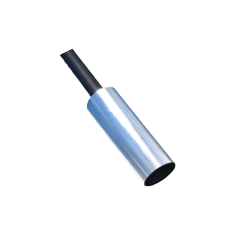
Before beginning the installation of a proximity sensor alarm delay circuit, it is crucial to have a comprehensive understanding of all system components. A typical setup includes a proximity sensor (inductive, capacitive, or photoelectric), a timing relay or a programmable logic controller (PLC) module configured for delay functions, the alarm indicator (such as a siren or beacon), and the necessary power supply units. The proximity sensor acts as the primary detection device, generating a signal when an object enters its sensing field. The core of the delay circuit is the timing device, which is programmed to introduce a specific time lag between the sensor's trigger signal and the activation of the alarm. This delay prevents nuisance alarms caused by transient or non-critical object movements. Engineers must verify the voltage and current ratings of all components to ensure compatibility and select appropriate wiring gauges and protective devices like fuses or circuit breakers.
Circuit Design and Schematic Review
A successful installation hinges on a correct and detailed circuit diagram. The schematic should clearly illustrate the connections between the sensor's output, the delay timer's input and output terminals, and the alarm device. Common configurations involve connecting the sensor's normally open (NO) or normally closed (NC) output to the trigger input of the delay timer. The timer's output relay contacts are then wired in series with the alarm device and the power source. For adjustable delay circuits, ensure the timer unit allows for easy setting of the delay period, often via a potentiometer or digital interface. It is advisable to include a manual bypass switch or test button in the design for functional testing and maintenance purposes. Review the schematic against the manufacturer's datasheets for pin configurations and operational logic to avoid wiring errors that could lead to malfunction or equipment damage.
Pre-Installation Safety and Preparation
Safety is the paramount concern in any electrical installation. Begin by ensuring all power sources to the control panel and machinery are locked out and tagged out (LOTO) according to standard safety protocols. Use a multimeter to confirm the absence of voltage on all terminals where work will be performed. Gather all required tools, including wire strippers, crimping tools, screwdrivers, and labeling equipment. Prepare the mounting locations for each component. Proximity sensors should be securely mounted on a stable surface, aligned correctly with the expected path of the target object, and within its specified sensing range and environmental limits (temperature, humidity, etc.). The timing relay or PLC should be installed in a protected enclosure, away from excessive heat, moisture, and electromagnetic interference. Proper preparation minimizes installation time and reduces the risk of errors.
Wiring and Connection Procedures
Execute the wiring meticulously based on the approved schematic. Start by running the power supply wires to the main disconnect and then to the power terminals of each component. Use color-coded wires consistently (e.g., black for line voltage, white for neutral, red for switched control signals) to aid in troubleshooting and future modifications. Connect the proximity sensor's power leads first. Then, run the sensor's output signal wire to the designated trigger input on the delay timer. Ensure all connections are tight and secure, using appropriate terminal blocks or connectors. Next, wire the output contacts of the delay timer to the alarm device. For the alarm circuit, consider adding an independent power indicator LED to visually confirm when the circuit is energized. Double-check every connection against the schematic before applying power. Proper wire management, including the use of cable ducts and ties, is essential for a professional and safe installation.
Configuration and Calibration of Delay Parameters
Once the hardware is installed and wired, the next critical step is configuring the delay timer. Power up the control circuit. Using the timer's interface (dials, buttons, or software), set the desired delay time. This period can range from milliseconds to several minutes, depending on the application's requirement to filter out brief, insignificant triggers. For instance, in a conveyor system, a delay of 2-3 seconds might be set to ignore small, bouncing products while alarming for a genuine jam. Test the calibration by manually triggering the sensor (using the target material) and measuring the time interval until the alarm activates with a stopwatch. Adjust the setting as necessary. If the timer has multiple modes (e.g., on-delay, off-delay, interval), verify that the correct mode is selected for the intended logic of the alarm circuit.
System Testing and Commissioning
Thorough testing validates the integrity and functionality of the entire installed system. Initiate a full operational test sequence. First, perform a dry run without machinery operation to test the sensor's detection and