Understanding Photoelectric Sensor Basics
Photoelectric sensors are indispensable components in modern industrial automation, used for detecting the presence, absence, or distance of objects without physical contact. They operate by emitting a beam of light (visible red, infrared, or laser) and detecting changes in the received light signal. The 24V DC variant is the industry standard for factory automation due to its compatibility with Programmable Logic Controllers (PLCs) and other control systems, offering a good balance between safety, noise immunity, and power efficiency. Before beginning any wiring procedure, it is paramount to consult the specific datasheet provided by the sensor manufacturer, as pin configurations and functions can vary between models (e.g., diffuse, retro-reflective, or through-beam types) and brands.
Essential Components and Safety Precautions
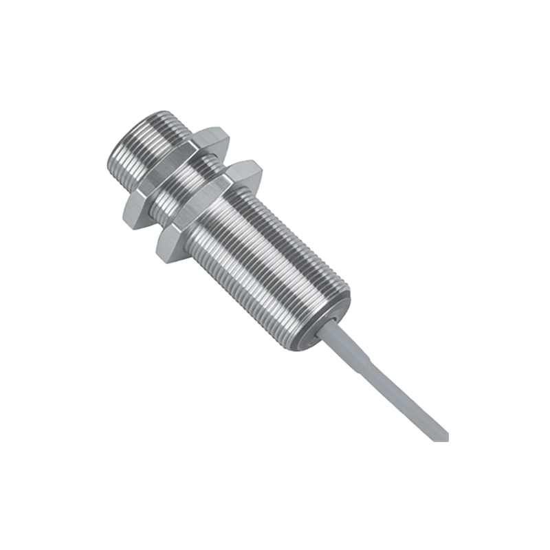
Gathering the correct components is the first critical step. You will need the 24V DC photoelectric sensor itself, a suitable 24V DC power supply (ensuring it can deliver the required current), a load device (such as a PLC input module, relay, or indicator lamp), and the appropriate wiring. Typically, multi-conductor shielded cable is recommended for noisy industrial environments. Safety cannot be overstated. Always disconnect and lock out all power sources before starting any wiring work. Verify the voltage ratings of all components. Wear appropriate personal protective equipment (PPE). Ensure your work area is clean, dry, and well-lit to prevent errors and accidents.
Standard Wiring Configuration for 3-Wire Sensors
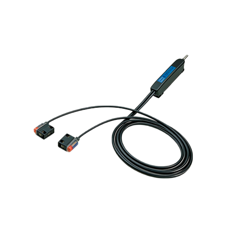
The vast majority of industrial 24V DC photoelectric sensors follow a 3-wire configuration. These wires are conventionally color-coded: Brown for the positive supply voltage (+V), Blue for the common negative or 0V (COM), and Black (or sometimes White) for the output signal (OUT). The output type is crucial: a PNP (sourcing) sensor switches the positive voltage to the load, while an NPN (sinking) sensor switches the negative path. For a standard PNP sensor connection: Connect the Brown wire to the +24V DC terminal of your power supply. Connect the Blue wire to the 0V/COM terminal of the same power supply. Finally, connect the Black output wire to one terminal of your load (e.g., PLC input). The other terminal of the load is then connected back to the 0V/COM of the power supply, completing the circuit.
Connecting to a PLC Input Module
Integrating the sensor with a PLC is a common task. The process depends on your PLC's input type (sinking or sourcing) and the sensor's output type. For a PNP sensor and a sinking PLC input (which is common), the wiring is straightforward. The sensor's Black output wire connects directly to the designated PLC input terminal. The PLC input's common point is connected to 0V. This creates a circuit where the PNP sensor "sources" current into the PLC's "sinking" input. If you have an NPN sensor, it must typically be connected to a sourcing-type PLC input card. Mismatching sensor and PLC input types will result in a non-functional circuit. Always cross-reference the PLC and sensor manuals.
Wiring 2-Wire (AC/DC) and 4-Wire Sensors
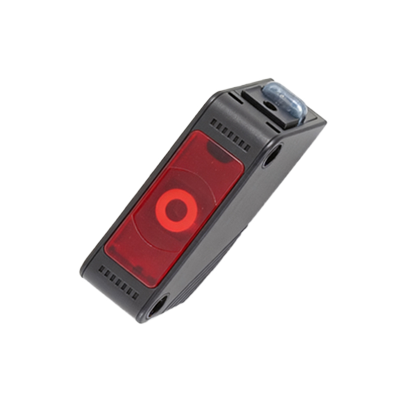
While less common in pure 24V DC systems, 2-wire sensors act like a switch in series with the power line and the load. They are simpler but have a residual voltage drop when on. For 4-wire sensors, which provide both a Normally Open (NO) and a Normally Closed (NC) output from the same unit, careful attention is needed. These sensors have the standard Brown (+V), Blue (COM), and then two output wires, often Black and White. One output is active when the target is detected, and the other is active when no target is present. This configuration is useful for fail-safe monitoring. The wiring principle remains: power the sensor correctly first, then connect the output wires to separate load channels as required by your control logic.
Shielding, Conduit, and Noise Mitigation
In industrial settings, electrical noise from motors, drives, and welding equipment can cause false triggering. Proper installation is key to reliability. Use shielded cable for all sensor connections. Connect the cable shield to a solid earth ground at one end only (usually the control panel end) to prevent ground loops. Run sensor cables separately from high-voltage power lines. If they must cross, do so at a 90-degree angle. Consider using conduit for physical protection and additional noise immunity. Ensure all connections are tight and secure to avoid intermittent faults. Implementing these best practices dramatically increases system stability.
Testing and Troubleshooting Common Issues
After wiring, apply power and perform a functional test. Use the sensor's built-in indicator LED (usually a green power LED and a yellow/orange output status LED) for initial diagnostics. A solid green light typically indicates correct power supply. The output LED should change state when an object is detected within the sensing range. If the sensor does not operate: First, double-check all wiring connections against the manual. Verify the power supply voltage is actually 24V DC at the sensor terminals using a multimeter. Confirm the sensing mode (light-on/dark-on) is correctly set via the sensor's teach button or rotary switches. Check for optical obstructions, dirty lenses, or an unsuitable target material/color. Ensure the load (e.g., PLC input) is functioning correctly by testing it with a known good signal.