Introduction to Photoelectric Sensor Line Tracking
Photoelectric sensor line tracking is a fundamental technology in industrial automation and robotics. It involves using photoelectric sensors to detect and follow a predefined path, typically a contrasting line on a surface. The core principle relies on the sensor's ability to distinguish between the reflectivity of the line and its background. When the sensor's emitted light beam hits the surface, the amount of reflected light varies depending on the color or material. This variation is converted into an electrical signal, which a controller interprets to determine the sensor's position relative to the line. This simple yet robust method enables precise guidance for automated guided vehicles (AGVs), assembly line robots, and various material handling systems, forming the backbone of countless automated processes.
Core Working Principles and Sensor Types
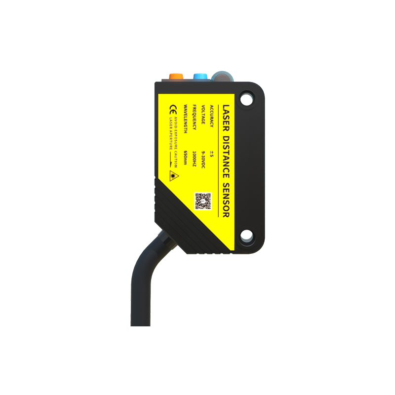
The operation hinges on the interaction between emitted light and the target surface. Common sensor types for line tracking include reflective (diffuse) sensors and retro-reflective sensors. Reflective sensors are most prevalent. They house both an emitter (usually an infrared LED) and a receiver (phototransistor or photodiode) in a single unit. The sensor emits a beam of light onto the surface. A white background reflects most of the light back to the receiver, generating a high signal. A dark line (e.g., black tape) absorbs most of the light, resulting in a low signal. The controller monitors this digital or analog signal transition to detect the line's edge. For enhanced precision in challenging environments, advanced sensors may use modulated light to filter out ambient light interference or employ multiple receiver elements to detect not just presence but also the position of the line within the sensor's field of view.
System Configuration and Layout Strategies
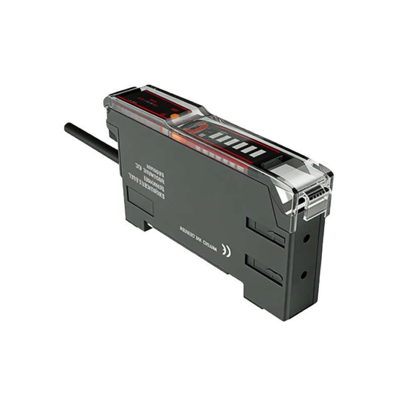
Effective line tracking systems require careful configuration of sensor arrays and their placement. A single sensor can only indicate if it is over the line or not, providing limited guidance. Therefore, arrays of multiple sensors are standard. A common configuration is a linear array of three to five sensors mounted side-by-side across the expected path of the line. The central sensor provides primary tracking data, while the outer sensors detect deviations—left or right of the center. The spacing between sensors and their height above the surface are critical parameters. The sensor's spot size must be smaller than the line width for accurate detection. The controller's algorithm interprets the pattern from the sensor array (e.g., [0, 1, 0] for centered) and generates corrective commands for the vehicle's or robot's drive motors to maintain alignment.
Key Performance Factors and Calibration
Several factors significantly impact tracking performance and reliability. Surface reflectivity and contrast are paramount; a high-contrast line on a consistent, non-reflective background yields the best results. Ambient light conditions can cause false readings, necessitating sensors with robust ambient light immunity or the use of physical shrouds. The speed of the vehicle must be matched with the sensor's response time and the controller's processing speed to prevent overshoot and oscillation. Regular calibration is essential. This involves setting the sensitivity threshold to correctly distinguish between the line and background under current operating conditions. For analog sensors, this means fine-tuning the threshold voltage. Environmental factors like dust, moisture, or surface wear can degrade performance, making periodic maintenance and recalibration a standard part of operational procedures.
Advanced Techniques and Algorithmic Control
Beyond basic on/off tracking, advanced techniques enhance capability. Proportional-Integral-Derivative (PID) control algorithms are widely used. Instead of simple "turn left/right" commands, a PID controller uses the analog signal value or the positional error from a multi-sensor array to calculate a proportional steering correction. This results in smoother, more precise tracking, especially on curved paths and at higher speeds. Some systems implement predictive algorithms or use cameras (a form of sophisticated photoelectric sensing) for complex path recognition, intersection handling, and color-coded instruction reading. Furthermore, the integration of photoelectric line tracking with other sensors, such as distance measurement sensors or inertial measurement units (IMUs), creates more intelligent and autonomous navigation systems capable of handling dynamic environments.
Common Industrial Applications and Use Cases
The applications of photoelectric line tracking are extensive. In manufacturing, AGVs follow floor-mounted tapes to transport materials between workstations, warehouses, and loading docks. Packaging and printing machinery use line tracking to ensure precise registration and alignment of materials. Robotic arms in assembly lines may use integrated line sensors to locate components on a conveyor belt. In the electronics industry, PCB handling equipment relies on this technology for accurate positioning. Outside traditional industry, educational robotics platforms and hobbyist projects frequently employ simple IR sensor arrays for line-following robot competitions, demonstrating the technology's accessibility and foundational role in mechatronics education.
Troubleshooting and Best Practices
Successful implementation requires adherence to best practices and systematic troubleshooting. Start with a high-contrast line; retro-reflective tape or painted lines on a matte floor are excellent choices. Ensure the sensor array is securely mounted and properly aligned perpendicular to the direction of travel. Common issues include erratic tracking due to incorrect sensitivity settings, inconsistent signals from a dirty sensor lens or degraded line, and mechanical issues like wheel slippage. A step-by-step diagnostic approach involves verifying sensor output signals with a monitor, checking for ambient light sources, inspecting the line path for damage or low contrast, and reviewing the control logic parameters. Implementing error-checking routines in the controller code, such as signal averaging or debouncing, can also improve robustness against transient noise.