Introduction to Proximity Sensor Switching
Proximity sensors are fundamental components in industrial automation, providing non-contact detection of objects. A critical aspect of their functionality lies in their output configuration, primarily defined as Normally Open (NO) and Normally Closed (NC). These terms describe the electrical state of the sensor's output switch in its non-activated, or "normal," condition. Grasping the distinction between NO and NC is essential for proper sensor selection, circuit design, and troubleshooting in control systems. This guide delves into the operational principles, typical applications, and wiring considerations for both configurations.
Defining Normally Open (NO) Operation
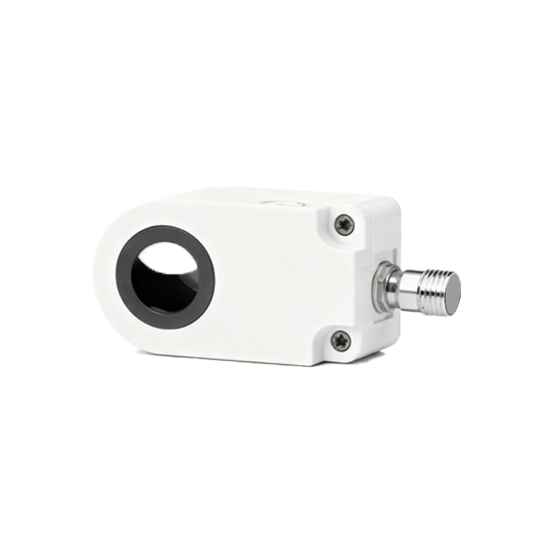
A Normally Open (NO) proximity sensor has an output circuit that is open (non-conductive) when no target is within its sensing range. In this state, no current flows through the output. When a valid target enters the detection field, the sensor activates and closes its internal switch, completing the circuit and allowing current to flow. From a logical standpoint, the NO output provides a signal (e.g., 24V DC) only upon detection. This "make on detection" behavior is intuitive for initiating actions, such as starting a process, incrementing a counter, or activating a solenoid when an object is present. It is often the default and most commonly used configuration for standard sensing tasks.
Defining Normally Closed (NC) Operation
Conversely, a Normally Closed (NC) proximity sensor has an output circuit that is closed (conductive) in its resting state, allowing current to flow when no target is detected. When a target enters the sensing range, the sensor opens the switch, interrupting the current flow. Logically, the NC output provides a signal that is present when the detection zone is clear and is removed upon detection. This "break on detection" characteristic is crucial for safety and monitoring functions. It is extensively used in applications where the absence of a signal indicates a fault or requires an immediate system halt, such as safety guarding, jam detection, or monitoring for part presence on a conveyor.
Key Differences and Electrical Characteristics
The core difference is the initial state of the output relay or solid-state switch. For an NO sensor, the output terminal is electrically floating or at a low potential when idle. For an NC sensor, the output terminal is typically at the supply voltage when idle. This has direct implications for wiring to a Programmable Logic Controller (PLC) input module. An NO sensor is typically wired to a sinking or sourcing input, providing voltage when activated. An NC sensor, when used for safety, is often wired in a series loop where a break in continuity (sensor activation) causes the PLC input to drop out, signaling a stop condition. Understanding the sensor's PNP (sourcing) or NPN (sinking) transistor output in conjunction with NO/NC is vital for correct integration.
Application Scenarios for NO and NC Configurations
Choosing between NO and NC depends on the required control logic and fail-safe considerations. NO sensors are ideal for standard counting, positioning, and process initiation. For example, detecting a bottle on a filling line to start the filler valve. NC sensors are preferred for safety interlocks and error detection. A classic application is on a protective guard door; an NC sensor ensures the machine cannot operate if the door is open (target absent, circuit closed). If the sensor fails or wiring is cut, the circuit opens, mimicking an "open door" state and causing a safe shutdown—a principle known as "fail-safe" design.
Wiring and Integration with Control Systems
Proper wiring is paramount. Datasheets clearly label the output terminal (e.g., brown wire: +V, blue wire: 0V, black wire: output). For a 3-wire DC sensor, the black wire's behavior changes. In NO mode, voltage appears on black when sensing. In NC mode, voltage is present on black when not sensing and disappears when sensing. When connecting to a PLC, confirm whether the input card is designed for a sourcing (PNP) or sinking (NPN) signal. Mismatching NO/NC logic in the PLC program with the physical sensor wiring is a common source of malfunction. Always verify the logic state at the input module during commissioning.
Fail-Safe Design and Sensor Diagnostics
The NC configuration is a cornerstone of fail-safe design. In critical monitoring, using an NC sensor means that a wire break, power loss, or sensor failure results in a loss of signal, which the control system can interpret as a fault condition, triggering a safe state. Modern sensors often feature diagnostic capabilities that can report such faults independently of the switching output.