Introduction to Two-Wire Proximity Sensors
In the realm of industrial automation, proximity sensors are indispensable components for non-contact object detection. Among the various configurations, the two-wire proximity sensor stands out for its simplicity and cost-effectiveness. Unlike their three-wire or four-wire counterparts, these sensors integrate the switching element directly into the power supply loop. This design eliminates the need for a separate signal wire, resulting in a more straightforward wiring scheme. The fundamental principle involves the sensor drawing a small leakage current when in the 'off' state and a higher load current when activated. This current change is detected by the connected controller, such as a PLC input module, to determine the sensor's state. Their robust construction and reduced installation complexity make them a preferred choice in numerous applications where space and budget are constrained.
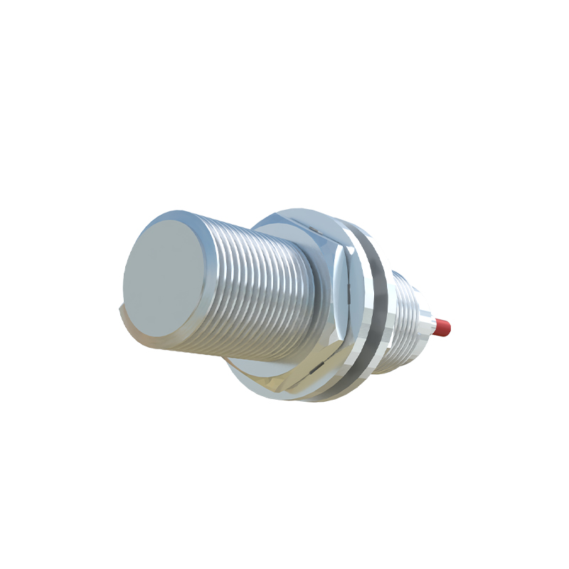
Operating Principle and Electrical Characteristics
The core functionality of a two-wire sensor revolves around its behavior as a variable current sink. In a typical DC system, the two wires connect in series with the load and the power supply. When no target is present, the sensor maintains a quiescent current, often below 2 mA, which is sufficient to power its internal electronics but low enough to be interpreted as an 'open' or 'off' state by the monitoring device. Upon detecting a target within its sensing range, the internal solid-state switch closes, allowing the full load current to flow. This current, typically ranging from a few milliamps to several hundred milliamps depending on the model, is recognized as the 'on' state. A critical consideration is the residual voltage drop across the sensor when active, known as the voltage drop or on-state voltage. This parameter must be accounted for to ensure the PLC input receives a voltage low enough to register as a logic '1' or 'high'.
Key Advantages Over Multi-Wire Sensors
The primary benefit of the two-wire design is its simplified installation. With only two connection points, wiring errors are minimized, installation time is reduced, and less cable is required, leading to lower overall project costs. This simplicity also translates to easier maintenance and troubleshooting. Furthermore, two-wire sensors often exhibit excellent resistance to electromagnetic interference (EMI) due to their simpler circuitry. They are inherently safe for use in series connections and can be easily integrated into existing two-wire control loops without significant redesign. Their compatibility with standard PLC digital inputs, designed to work with dry contacts or two-wire devices, is another significant advantage, offering great flexibility in system design.
Important Selection Criteria and Limitations
Selecting the appropriate two-wire proximity sensor requires careful analysis of several parameters. First, the sensor's voltage drop must be less than the 'off' voltage threshold of the connected controller input. Second, the quiescent current must be high enough to power the sensor but low enough not to falsely trigger the input module. The load current rating must not be exceeded, and the minimum operating current must be met to ensure reliable switching. A notable limitation is that two-wire sensors generally have a lower switching frequency compared to three-wire versions due to internal circuitry requirements for power management. They also may not be suitable for applications requiring very low leakage current or where the connected load has a very high impedance. Understanding the specific electrical characteristics of both the sensor and the controller is paramount for successful implementation.
Common Applications in Industrial Settings
Two-wire proximity sensors find widespread use across diverse industries. They are commonly employed for basic presence detection tasks, such as counting objects on a conveyor belt, detecting the position of a machine part like a cylinder rod, or confirming the open/closed status of a door or guard. Their robust nature makes them ideal for harsh environments in material handling, packaging, and automotive assembly lines. They are frequently used in control panels for status indication and in modular machine designs where quick connectivity is essential. The ability to connect multiple sensors in series, while observing current limitations, allows for efficient monitoring of multiple points with a single controller input, further enhancing their utility in cost-sensitive applications.
Installation and Wiring Best Practices
Proper installation is crucial for reliable operation. Always refer to the manufacturer's datasheet for specific wiring diagrams and electrical specifications. Use shielded cables in environments with high electrical noise, and ground the shield at the controller end only. Ensure the power supply voltage is stable and within the sensor's specified range. Pay close attention to polarity for DC sensors; incorrect connection can permanently damage the device. Maintain the recommended sensing distance and be mindful of the sensor's mounting material, as certain metals can influence the sensing range. For inductive sensors, ensure the target material is ferrous (like steel) for the specified sensing distance. Regular testing under normal