Introduction to Photoelectric Sensor Control Circuits
Photoelectric sensor control circuits are fundamental components in modern industrial automation, enabling non-contact detection of objects based on light modulation. These circuits form the critical interface between the sensing element and the control system, translating a light signal into a reliable electrical output. The core principle involves a light emitter, typically an LED, and a receiver, such as a phototransistor or photodiode. The control circuit's primary function is to power the emitter, condition the receiver's signal, and produce a clean, stable digital or analog output for programmable logic controllers (PLCs), microcontrollers, or other control devices. Understanding the various circuit configurations is essential for selecting the right sensor for applications ranging from object counting and positioning to edge detection and safety curtains.
Key Components and Their Functions
A standard photoelectric sensor control circuit comprises several key components. The emitter side features a current-limiting resistor in series with the light-emitting diode (LED) to ensure stable operation and longevity. On the receiver side, the photodetector converts incoming light intensity into a proportional current. Following this, an amplification stage, often using operational amplifiers (op-amps), is crucial for boosting the weak signal from the photodetector to a usable level. A comparator circuit is then typically employed to convert the analog signal into a crisp digital high/low output by comparing it to a preset threshold voltage. Finally, output stages may include transistors (like BJTs or MOSFETs) for switching heavier loads, and protective elements such as flyback diodes for inductive loads or filters for noise suppression in electrically noisy industrial environments.
Through-Beam Sensor Circuit Configuration
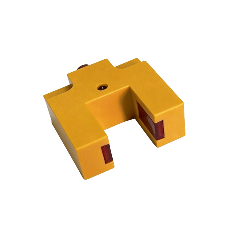
Through-beam (or opposed) sensors offer the longest sensing ranges and highest reliability. The control circuit for this type is often separated into two distinct units: a transmitter and a receiver. The transmitter circuit is a simple constant-current driver for the LED. The receiver circuit, however, requires high sensitivity. It commonly uses a phototransistor in a common-emitter configuration. The collector output is fed into a high-gain amplifier and then a comparator with hysteresis (Schmitt trigger) to prevent output oscillation when the detected light level is near the threshold. This design ensures a definitive on/off signal even in the presence of dust or minor misalignment, making it ideal for precise detection tasks on assembly lines or in packaging machinery.
Reflective and Diffuse Sensor Circuit Designs
Reflective and diffuse sensors house both emitter and receiver in a single housing, simplifying installation. Their control circuits are more complex due to the need to distinguish the reflected signal from ambient light. A common technique involves modulating the emitted light at a specific high frequency (e.g., several kHz). The receiver circuit is then tuned with a band-pass filter or a synchronous demodulator to respond only to light pulsed at that same frequency. This modulation technique effectively cancels out the influence of constant ambient light from factory lamps or sunlight, significantly improving signal-to-noise ratio and operational stability in variable lighting conditions. The comparator threshold in these circuits is carefully set to differentiate between the presence and absence of the target object.
Analog Output and Background Suppression Circuits
Beyond simple on/off detection, many applications require analog output or precise distance measurement. Analog output circuits for photoelectric sensors linearize the photodetector's response to provide a voltage or current (e.g., 0-10V, 4-20mA) proportional to the received light intensity or distance. Background suppression sensors, a specialized type of diffuse sensor, use triangulation principles. Their control circuit incorporates a position-sensitive detector (PSD) or a specialized receiver array. The circuit analyzes the spot where the reflected light falls on the detector to determine distance, effectively ignoring objects beyond a user-set range. This requires sophisticated signal processing, often handled by dedicated integrated circuits (ICs) that calculate the centroid of the light spot.
Circuit Protection and Noise Immunity Considerations
Industrial environments are harsh, necessitating robust circuit design. Protection against voltage transients is achieved with Transient Voltage Suppression (TVS) diodes and RC snubber networks. Reverse polarity protection is often implemented using a series diode. For noise immunity, especially in circuits with long cable runs, techniques include using twisted-pair cables, implementing low-pass filters in the signal path, and employing differential line drivers/receivers for analog signals. Proper grounding and shielding are paramount. Many modern sensor ICs integrate much of this protection and signal conditioning, simplifying design but requiring engineers to adhere strictly to the manufacturer's layout and filtering recommendations for optimal performance.
Integration with Programmable Logic Controllers (PLCs)
The final stage of the control circuit is interfacing with the broader control system. For digital sensors, the output is typically a solid-state NPN (sinking) or PNP (sourcing) transistor configuration compatible with PLC digital input modules. The circuit includes a pull-up or pull-down resistor as required. Some sensors feature programmable outputs via IO-Link, a point-to-point serial communication protocol. In this case, the control circuit includes a microcontroller and an IO-Link transceiver chip, allowing parameters like sensitivity, output mode, and timing functions to be set digitally. This represents the convergence of traditional sensor circuitry with digital networking, enabling advanced diagnostics and easier system integration.
Conclusion and Future Trends
Photoelectric sensor control circuits have evolved from simple discrete designs to highly integrated, intelligent systems. The fundamental blocks of emitter drive, signal conditioning, and output switching remain, but implementation has shifted towards application-specific integrated circuits (ASICs) and microcontrollers. Future trends point toward increased miniaturization, lower power consumption, and enhanced communication capabilities like IO-Link and integration into Industrial Internet of Things (IIoT) frameworks. Engineers must balance classic electrical design principles with an understanding of digital communication protocols to effectively implement these advanced sensors. A thorough grasp of the underlying circuit diagrams remains indispensable for troubleshooting, customization, and optimizing sensor performance in complex automation solutions.