Introduction to Inductive Proximity Sensing
Inductive proximity sensors are fundamental components in modern industrial automation, providing non-contact detection of metallic objects. The PT08-104N0 represents a specific model within this broad category, designed for reliable performance in demanding environments. These sensors operate on the principle of electromagnetic induction. An internal oscillator generates a high-frequency electromagnetic field that radiates from the sensor's active face. When a metallic target enters this field, eddy currents are induced on the target's surface. This causes a change in the oscillation amplitude within the sensor, which is detected by a threshold circuit, subsequently triggering a solid-state output switch. This mechanism allows for precise, wear-free detection, making sensors like the PT08-104N0 ideal for counting, positioning, and end-of-travel limit applications.
Key Specifications of the PT08-104N0 Model
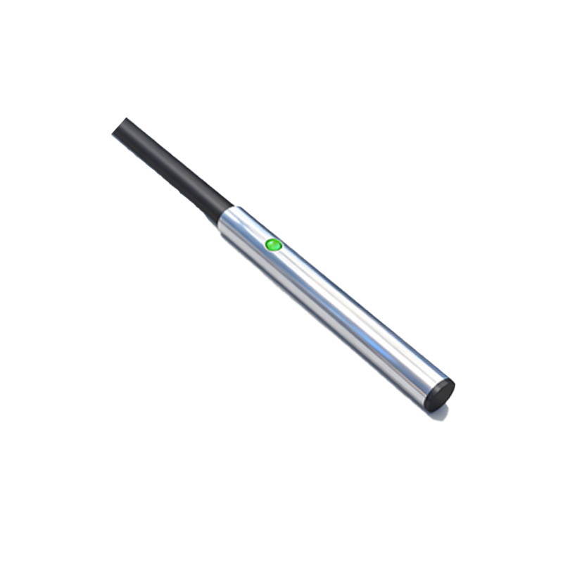
The PT08-104N0 is typically characterized by several critical electrical and mechanical parameters. It is an 8mm diameter cylindrical sensor, often in a shielded or flush-mountable design, allowing for side-by-side installation without mutual interference. The operating voltage range commonly spans from 10-30V DC, making it compatible with standard industrial control voltages. Its output is normally a 3-wire configuration (brown for +V, blue for 0V, black for output signal) with a PNP (sourcing) transistor switch, capable of sinking up to 200mA of current, sufficient to drive relays, PLC inputs, or small solenoids directly. The nominal sensing distance, or Sn, for this 8mm model is typically 2mm for mild steel, with a reduction factor applied for other metals like stainless steel, aluminum, or copper.
Environmental and Performance Characteristics
Robust construction is a hallmark of industrial sensors like the PT08-104N0. It usually features a housing made of nickel-plated brass or stainless steel, offering high resistance to corrosion, oils, and coolants. The sensing face is often a rugged PBT or similar plastic. These sensors are designed to operate across a wide temperature range, from -25°C to +70°C, ensuring functionality in both cold storage and hot machinery environments. Key performance metrics include a high switching frequency, often up to 1 kHz, enabling detection of rapidly moving parts on conveyor lines. Additionally, features like short-circuit and reverse polarity protection are standard, safeguarding the sensor and the control circuit from accidental wiring errors.
Application Scenarios in Automation Systems
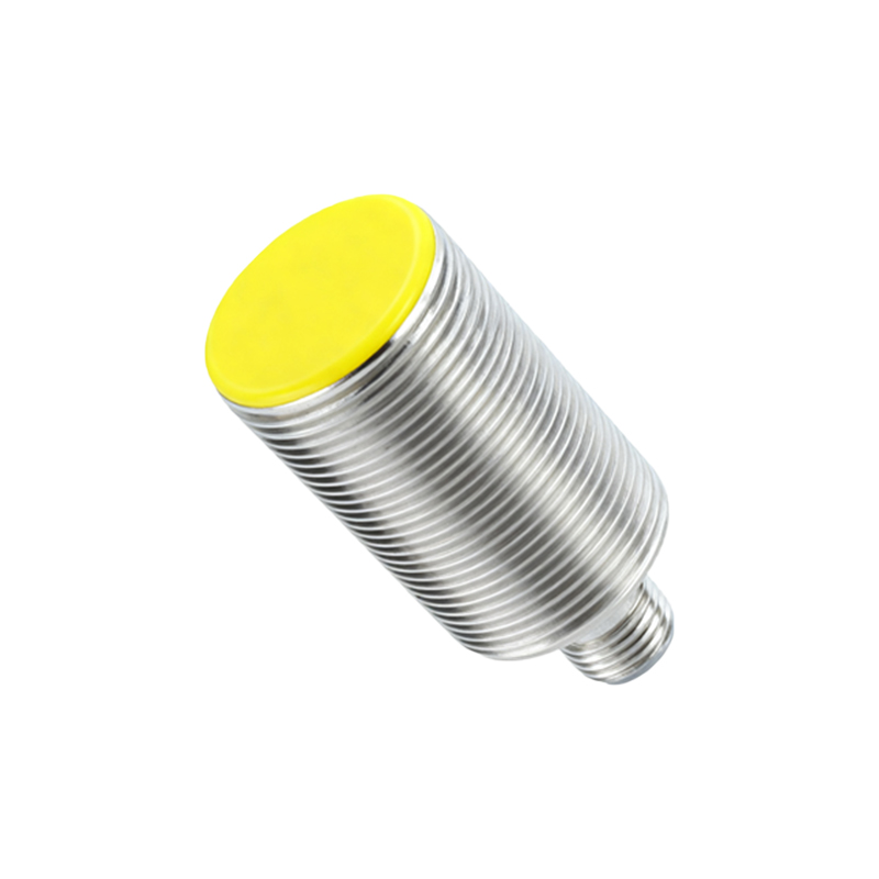
The PT08-104N0 finds extensive use across various industrial sectors. In automotive assembly, it verifies the presence of metal components like pistons or bolts before a robotic welding operation. On packaging machinery, it detects the metallic foil on product labels for precise cutting or filling control. Within material handling, these sensors monitor the position of metal pallets or actuator cylinders, providing feedback to the PLC for sequential logic control. Its compact size and flush-mounting capability make it perfect for integration into tight spaces on machine tools, such as detecting the home position of a spindle or confirming the closure of a metal safety guard.
Installation and Wiring Considerations
Proper installation is crucial for optimal performance. For flush-mountable models, they can be embedded in metal brackets without affecting the sensing range. Non-flush (unshielded) models require a clearance zone around the sensor face. The target material and size significantly influence the effective sensing distance; the target should be at least equivalent to the sensor's face diameter. For wiring, the brown wire connects to the positive DC supply, blue to the negative or ground, and the black output wire connects to the load (e.g., a PLC input). A load, such as a resistor, must always be connected in series with the output. Ensuring a stable, clean power supply with proper filtering minimizes electrical noise interference, which is critical in environments with variable frequency drives or large motors.
Diagnostics and Troubleshooting Tips
When a PT08-104N0 sensor malfunctions, a systematic approach is required. First, verify the power supply voltage at the sensor's terminals with a multimeter. Next, check the output state by observing the indicator LED (if present) or measuring the voltage on the output wire with and without a target present. False triggers can be caused by vibration, accumulation of metallic dust on the face, or interference from adjacent sensors or power cables. Ensure the target is within the specified sensing range and is made of a detectable material. If the sensor is damaged mechanically or by excessive current, replacement is often the most efficient solution given the sensor's typical design as a sealed, non-serviceable