Understanding Sensitivity Adjustment in Photoelectric Sensors
Photoelectric sensors are fundamental components in industrial automation, detecting the presence, absence, or position of objects using a light transmitter and receiver. The core of reliable operation lies in precise sensitivity adjustment. This setting determines the threshold at which the sensor's output switches state. If set too high, the sensor may trigger on background noise or dust; if set too low, it might fail to detect the target object. Most modern photoelectric sensors feature a potentiometer, a teach-in button, or digital interfaces for this calibration. The adjustment process varies slightly between diffuse, retro-reflective, and through-beam sensor types, but the underlying principle remains consistent: achieving a stable signal margin between the "object present" and "object absent" states.
Essential Tools and Preliminary Safety Checks
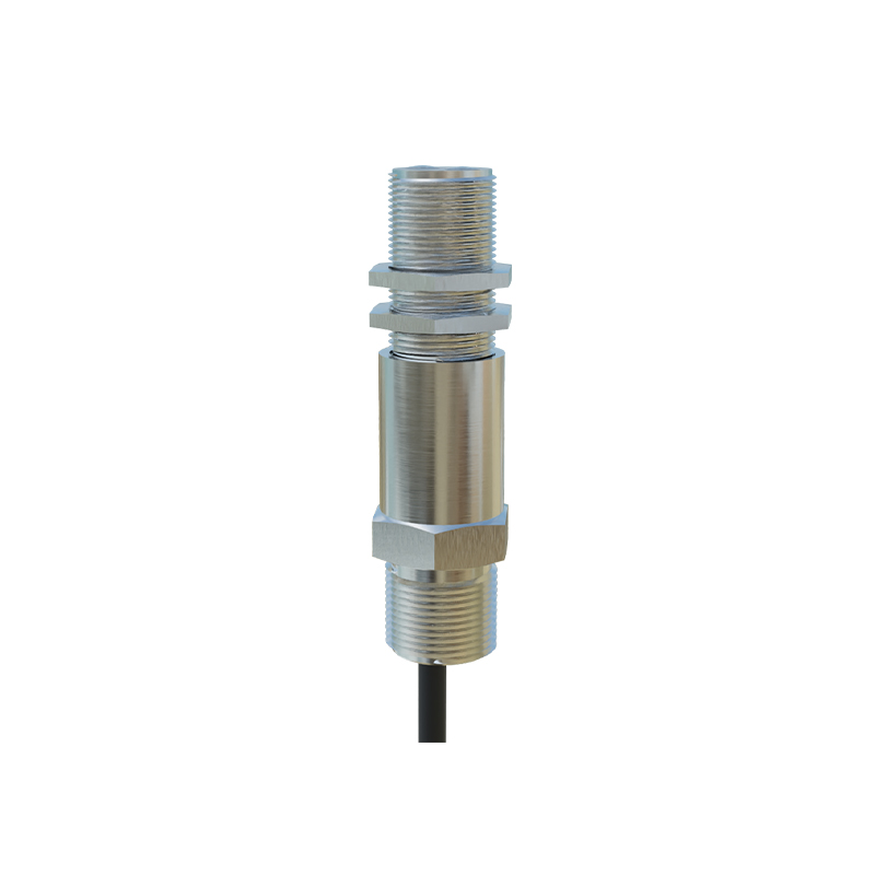
Before beginning any adjustment, ensure a safe working environment. De-energize the machinery or implement appropriate lockout/tagout (LOTO) procedures to prevent accidental startup. The primary tool is the sensor's data sheet or manual, which provides the specific adjustment procedure and indicator light meanings. For initial setup, you may need the target object itself. Visually inspect the sensor lens for dirt, oil, or damage, and clean it with a soft cloth if necessary. Verify the sensor is correctly mounted and aligned, especially for through-beam and retro-reflective types. Power the system back on only after these checks are complete, observing the sensor's status LED for its startup sequence.
Step 1: Establishing the Reference States
The first step is to create a baseline. With the sensor powered, observe the output indicator LED (often separate from the power LED). Position the standard target object at the nominal sensing distance as specified in the datasheet. Note the state of the indicator. Now, remove the target object completely from the sensing field. You have now established two key reference points: the "object present" condition and the "object absent" condition. For some sensors, especially background suppression types, you may also need to establish a "background" reference. The goal of adjustment is to ensure the sensor reliably distinguishes between these states under all expected operating conditions.
Step 2: The Adjustment Procedure Using a Potentiometer
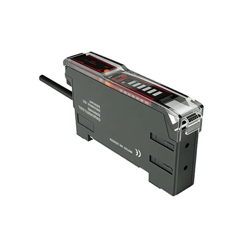
For sensors with a rotary potentiometer, locate the adjustment screw, typically marked "SENS" or with a plus/minus symbol. Using a small screwdriver, turn the screw slowly clockwise to increase sensitivity (counter-clockwise to decrease). Begin with the target object absent. Adjust the sensitivity downward until the output indicator just switches to the "absent" state. Then, slowly introduce the target object. The indicator should switch reliably. Next, test the margin. With the object present, slightly decrease sensitivity until the indicator flickers or switches off, then increase it back by a quarter to half turn to create a stable buffer. This margin accounts for environmental changes like temperature drift or minor lens contamination.
Step 3: Utilizing the Teach-In or Push-Button Method
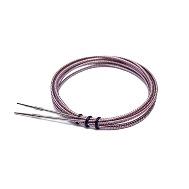
Many contemporary sensors feature a push-button or teach-in function for simplified setup. The exact sequence is model-specific, so consult the manual. A common two-point teach-in process involves: First, with no target in the sensing area, press and hold the button until the indicator flashes (this teaches the "background" level). Second, place the target object in position and press the button again (this teaches the "object" level). The sensor's internal microprocessor automatically calculates and sets the optimal switching point midway between these two taught values. This method is highly effective for diffuse sensors dealing with varying surface colors or reflectivities.
Step 4: Verification and Stability Testing
After adjustment, rigorous testing is crucial. Perform multiple detection cycles with the target object at the closest, nominal, and farthest specified distances. Vary the approach speed if applicable. Introduce potential real-world interferences: simulate ambient light changes, gently vibrate the mounting bracket, or pass non-target objects near the sensing beam. The sensor's output should remain stable and correct throughout these tests. Observe the indicator LED for any flickering, which suggests the sensitivity is set at a critical threshold and requires a slight increase in margin. Document the final potentiometer position or teach-in settings for future reference.
Step 5: Troubleshooting Common Adjustment Issues
If stable adjustment proves difficult, systematic troubleshooting is required. Unstable switching often points to insufficient signal strength. Check for misalignment, a dirty lens, or an unsuitable target (too small, too dark, or highly reflective at an angle). Electrical noise from nearby motors or drives can also cause erratic behavior; ensure proper shielding and grounding of cables. If the sensor triggers without a target, it may be detecting background objects or reflections. For diffuse sensors, consider using a model with background suppression. For retro-reflective types, ensure the reflector is clean and use a polarizing filter if detecting shiny objects. Always revert to the sensor's diagnostic indicators, as specific flash patterns often denote problems like overload or short circuit.
Best Practices for Long-Term Reliability
Once optimally adjusted, implement practices to maintain performance. Schedule regular preventive maintenance to clean lenses and check mounting stability. Monitor the operating environment for significant changes in temperature, humidity, or ambient light that could affect sensitivity. For critical applications, consider sensors with automatic sensitivity compensation or IO-Link functionality, which allows for digital monitoring of the received signal strength and remote adjustment. Proper adjustment is not a one-time task but part of an ongoing reliability strategy, ensuring photoelectric sensors continue to provide accurate, fail-safe detection throughout their service life.