Understanding the 3-Wire Proximity Sensor Configuration
A 3-wire proximity sensor is a fundamental component in industrial automation, commonly used for non-contact detection of metallic or non-metallic objects. Unlike 2-wire sensors that are wired in series with the load, the 3-wire version provides a more stable and reliable signal, making it a preferred choice for precise control applications. The three wires are typically color-coded: brown for positive supply voltage, blue for negative or common (0V), and black for the output signal. This configuration is standard for both NPN (sinking) and PNP (sourcing) sensor types, which determine the current flow direction of the output. Understanding this basic wiring scheme is crucial before proceeding to physical connections, as incorrect wiring can lead to sensor damage or system malfunction.
Identifying Sensor Type: NPN vs. PNP
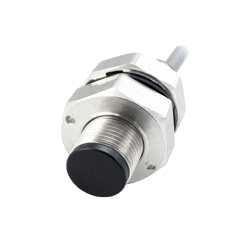
Before initiating any wiring, it is essential to determine whether your proximity sensor is an NPN or PNP type, as this dictates how the output wire connects to the control system. An NPN sensor, also known as a sinking sensor, switches the negative side of the load. When activated, it connects the black output wire to the blue wire (common negative), allowing current to flow from the load into the sensor. Conversely, a PNP sensor, or sourcing sensor, switches the positive side. Upon detection, it connects the black output wire to the brown wire (positive supply), sourcing current from the sensor to the load. This distinction is critical for compatibility with programmable logic controllers (PLCs) or other control devices, which are often designed to accept either sinking or sourcing inputs. Always refer to the sensor's datasheet or labeling to confirm its type.
Step-by-Step Wiring Procedure
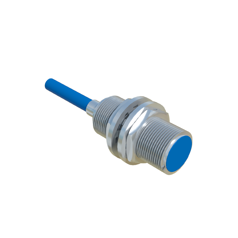
To wire a 3-wire proximity sensor correctly, follow these systematic steps. First, ensure the power supply is disconnected to prevent electrical hazards. Identify the power source, typically a 10-30V DC supply, and connect the brown wire to the positive terminal (+) and the blue wire to the negative terminal (-). For the output connection, link the black wire to the input of your control device, such as a PLC input module. If using an NPN sensor, connect the black wire to the PLC input, and ensure the PLC common is tied to positive voltage. For a PNP sensor, connect the black wire to the PLC input, with the PLC common connected to negative. Double-check all connections for tightness and correctness, as loose wires can cause intermittent failures. Once secured, apply power and test the sensor by bringing a target object within its sensing range, observing the output indicator LED if available.
Common Wiring Diagrams and Examples
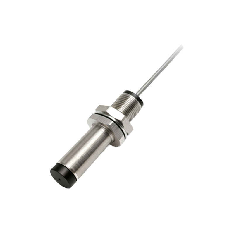
Visual aids can greatly assist in proper installation. For an NPN sensor, a typical diagram shows the brown wire to +24V DC, blue wire to 0V DC, and black wire to the PLC input, with the PLC common connected to +24V DC. This setup allows the sensor to sink current to ground when activated, pulling the PLC input low. For a PNP sensor, the diagram is similar, but the black wire sources current to the PLC input, with the PLC common linked to 0V DC, causing the input to go high upon detection. In applications involving relay loads, the black wire may connect directly to the relay coil, with the other coil terminal tied to the opposite supply polarity based on sensor type. Always ensure the load (PLC, relay, etc.) is rated within the sensor's output specifications, including voltage and current limits, to avoid overload.
Troubleshooting and Best Practices
Even with correct wiring, issues may arise. If the sensor fails to operate, first verify the power supply voltage with a multimeter to ensure it falls within the sensor's operating range (e.g., 12-24V DC). Check for loose connections or damaged wires, particularly at terminal points. Confirm the sensing distance and target material compatibility, as some sensors only detect specific metals. For false triggers, ensure there is no electrical noise interference by using shielded cables and grounding the shield properly. As best practices, always follow manufacturer guidelines, use appropriate wire gauges (e.g., 18-22 AWG for low-current signals), and label wires clearly for future maintenance. Regularly inspect sensors in harsh environments for debris or corrosion that could affect performance. Implementing these measures enhances system reliability and longevity.
Applications and Industry Considerations
3-wire proximity sensors are versatile and widely used across various industries, including automotive manufacturing, packaging, and material handling. They serve functions such as object