Introduction to Inductive Proximity Sensing
Inductive proximity sensors are fundamental components in modern industrial automation, renowned for their reliability, durability, and non-contact detection capabilities. These sensors operate on the principle of electromagnetic induction to detect the presence or absence of metallic objects without any physical contact. The core of the sensor consists of a coil wound around a ferrite core, an oscillator, a detection circuit, and an output circuit. When an alternating current flows through the coil, it generates a high-frequency oscillating electromagnetic field at the active face of the sensor. This field is the key to its detection mechanism, extending a short distance from the sensor's surface. The robust construction, typically housed in a metal or polymer casing, makes them ideal for harsh industrial environments where dust, oil, and vibration are prevalent. Their primary function is to provide a switching signal, making them indispensable for tasks like counting, positioning, and end-of-travel detection in machinery.
Core Operating Principle: Eddy Current Damping
The fundamental working principle hinges on the phenomenon of eddy current damping. When a conductive metal target enters the oscillating electromagnetic field, electromagnetic induction occurs. According to Faraday's law, eddy currents are induced on the surface of the target object. These circulating currents create their own magnetic field, which opposes the original field generated by the sensor coil, following Lenz's law. This opposition results in a damping or loading effect on the oscillator circuit. The energy loss due to this damping causes a measurable decrease in the amplitude of the oscillation. The sensor's internal detection circuit continuously monitors this amplitude. Once the damping exceeds a predefined threshold—corresponding to the sensor's nominal sensing distance—the circuit triggers a state change in the output signal. For non-conductive materials like plastic, wood, or ceramics, no significant eddy currents are generated, and thus no detection occurs, defining the sensor's limitation to metallic targets.
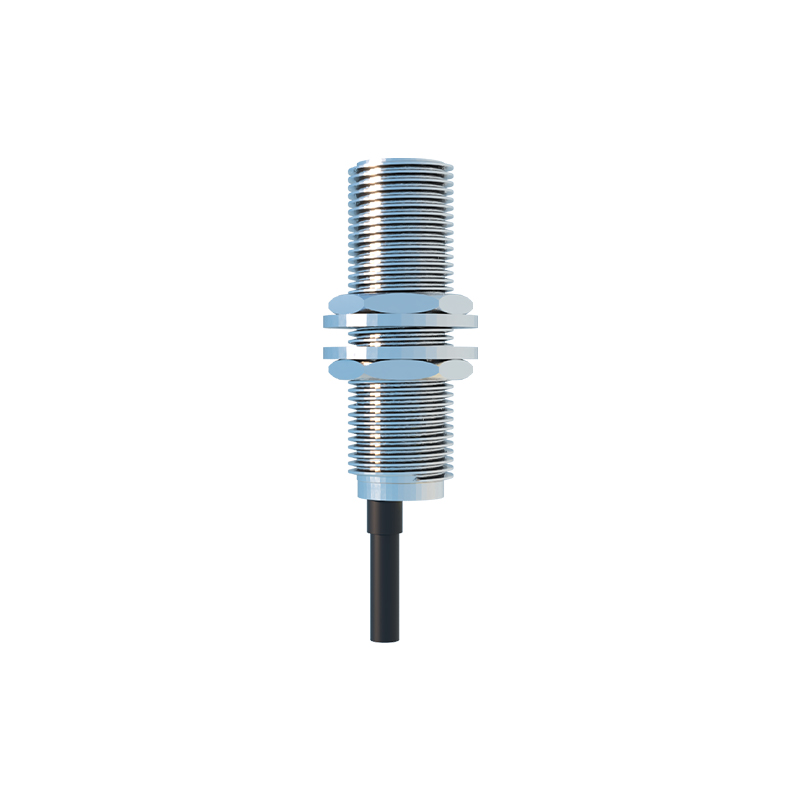
Sensor Construction and Key Components
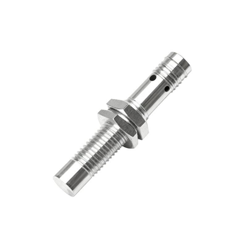
Internally, an inductive proximity sensor is a sophisticated assembly of electronic and magnetic components. The heart is the coil and ferrite core assembly, which determines the field's shape and strength. This coil is part of a resonant LC tank circuit driven by a high-frequency oscillator, often operating in the range of 100 kHz to 1 MHz. The detection circuit, which can be based on amplitude demodulation or phase shift analysis, is critically sensitive to changes in the oscillator's condition. A Schmitt trigger provides hysteresis, ensuring a clean, bounce-free output switch despite minor fluctuations in the target position or environmental noise. The output stage typically features solid-state switches like transistors (for DC sensors) or triacs (for AC sensors), providing a digital ON/OFF signal. Modern sensors often include protection circuits against short-circuits, reverse polarity, and voltage spikes, alongside LED status indicators for diagnostics.
Factors Influencing Sensing Performance
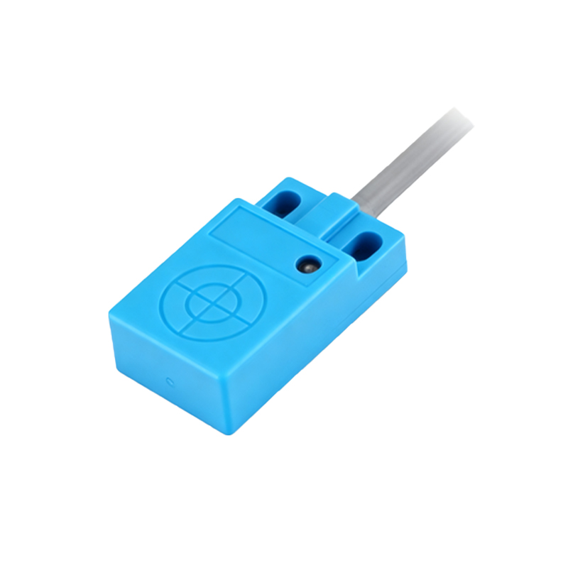
Several critical factors determine the effective sensing range and performance of an inductive proximity sensor. The first is the target material. Ferrous metals (like mild steel) induce the strongest eddy currents and provide the standard sensing distance (Sn). Non-ferrous metals (like aluminum, copper, or brass) have different electrical conductivities and permeabilities, resulting in a reduced effective sensing distance, often requiring correction factors (typically 0.3 to 0.8 x Sn). The target size and shape are also crucial; the target should generally be at least equivalent to the sensor's face diameter for the rated sensing distance. Thickness is important too, as very thin targets may not provide sufficient material for adequate eddy current generation. Furthermore, the installation environment matters. Adjacent metallic objects or sensors mounted flush to metal can reduce the effective range due to side-field interference, whereas non-flush mounting allows the full field to develop. Operating temperature and supply voltage stability also affect performance consistency.
Output Configurations and Wiring
Inductive proximity sensors are available in various output configurations to interface seamlessly with control systems like PLCs (Programmable Logic Controllers). The two primary types are DC (sinking or sourcing) and AC/DC (universal) models. DC sensors are commonly available in 3-wire configurations: PNP (sourcing) and NPN (sinking). A PNP sensor switches the positive voltage to the load, while an NPN switches the negative or ground line. The choice depends on the input circuit of the controller. Two-wire AC/DC sensors are simpler to wire, acting like a switch in series with the load and power supply, but they have a residual leakage current even in the "off" state. Analog output versions (4-20 mA or 0-10V) also exist, providing a continuous signal proportional to the distance to the target,