Introduction to Inductive Proximity Sensors
Inductive proximity sensors are fundamental components in industrial automation, widely used for non-contact detection of metallic objects. These sensors operate on the principle of electromagnetic induction, generating an oscillating electromagnetic field from a coil. When a metallic target enters this field, eddy currents are induced, causing a change in the oscillation amplitude. This change is detected by the sensor's circuitry, triggering a switching output. The reliability, durability, and high-speed response of inductive sensors make them indispensable in applications like position sensing, object counting, and machine safety. Understanding their wiring is crucial for correct installation, optimal performance, and system integration.
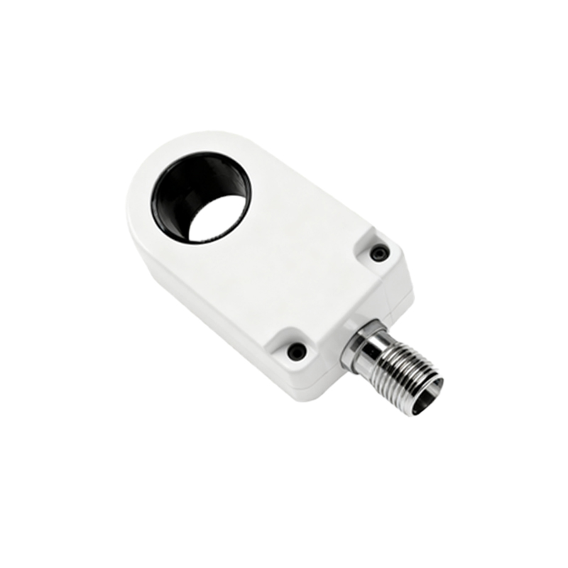
Core Components and Electrical Characteristics
A standard three-wire DC inductive proximity sensor typically comprises three terminals: brown (positive supply, +V), blue (common negative or 0V), and black (switched output). The sensor requires a DC power supply, commonly 10-30 VDC. The black wire provides the output signal, which can be either a PNP (sourcing) or NPN (sinking) transistor configuration. In a PNP configuration, the output switches the positive voltage to the load; in an NPN, it switches the negative. Two-wire AC/DC sensors also exist, integrating directly into the load circuit but with considerations for leakage current. Key electrical specs include operating voltage range, output current capacity, switching frequency, and protection against short-circuit, reverse polarity, and overload.
Standard Three-Wire DC Wiring Diagram
The most common wiring setup involves a three-wire DC sensor. For a PNP (normally open) sensor: Connect the brown wire to the positive terminal of the DC power supply (e.g., +24VDC). Connect the blue wire to the negative terminal (0VDC). The black output wire connects to one terminal of the load (e.g., a PLC input, relay coil, or indicator lamp). The other terminal of the load is then connected to the power supply's negative (0VDC). When a metal target is detected, the PNP transistor activates, sourcing current from the brown line through the black wire to the load, completing the circuit to negative. For an NPN (normally open) sensor, the wiring is similar, but the blue wire connects to negative, the brown to positive, and the black output connects to the load, which is then linked to positive. The NPN sinks current to ground when activated.
Two-Wire Sensor Wiring Configuration
Two-wire sensors simplify wiring by operating in series with the load, functioning for both AC and DC supplies. They have only two connection wires, typically brown and blue. The sensor acts as a switch that closes upon detection. For a DC circuit, connect the brown wire to the positive side of the power supply and the blue wire to one side of the load. The other side of the load connects to the supply negative. In an AC circuit, one wire connects to the phase (hot) line, and the other to the load, which then connects to the neutral. A critical consideration is the residual current or leakage current present even when the sensor is off, which must be accounted for to prevent unintended activation of sensitive loads like PLC inputs. A bypass resistor may be required.
Wiring for Complementary (NO and NC) Outputs
Some advanced inductive sensors feature both normally open (NO) and normally closed (NC) outputs, often with four wires: brown (+V), blue (0V), black (NO output), and white (NC output). This provides flexibility for control logic. The wiring follows the same principle: power the sensor via brown and blue. The black NO wire connects to a load that should be energized upon target detection. The white NC wire connects to a separate load that is energized when no target is present and de-energizes upon detection. This configuration is valuable for safety circuits or applications requiring a fail-safe signal. Ensure the total load on both outputs does not exceed the sensor's overall current rating.
Shielded vs. Unshielded Sensor Wiring Considerations
Inductive sensors come in shielded (flush-mountable) and unshielded (non-flush) designs, which influence installation but not the core wiring diagram. Shielded sensors can be mounted flush in metal without affecting their sensing field, making them ideal for tight spaces. Unshielded sensors have a larger sensing range but require a non-metallic surround. Electrically, wiring is identical. However, in environments with strong electromagnetic interference (EMI), using shielded cable for the sensor connections and properly grounding the shield at the controller end is recommended to prevent signal noise and