Laser proximity sensors are essential components in modern automation, offering precise non-contact detection for various industrial applications. Proper wiring is critical to ensure reliable operation, safety, and longevity of these devices. This guide provides a step-by-step approach to wiring laser proximity sensors, covering key principles and practical considerations.
First, identify the sensor type. Laser proximity sensors typically come in two main configurations: PNP (sourcing) and NPN (sinking). PNP sensors switch the positive voltage to the load, while NPN sensors switch the negative voltage. Check the sensor datasheet or labeling to confirm the type, as incorrect identification can lead to malfunction or damage.

Next, prepare the necessary tools and components. You will need a DC power supply matching the sensor's voltage rating (commonly 12-24V DC), appropriate cables, wire strippers, and a multimeter for verification. Always disconnect power before starting any wiring work to prevent electrical hazards.
The wiring process involves three main connections: power, output, and ground. For a typical three-wire DC sensor:
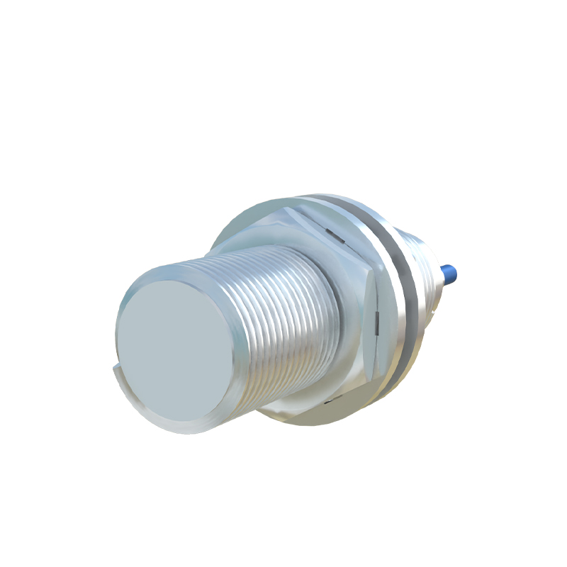
1. Connect the brown wire (or red wire, depending on the manufacturer) to the positive terminal of the power supply.
2. Connect the blue wire (or black wire) to the negative terminal or ground.
3. Connect the black wire (or white wire) to the load, such as a PLC input, relay, or indicator. The load is then linked to the opposite power supply terminal to complete the circuit.
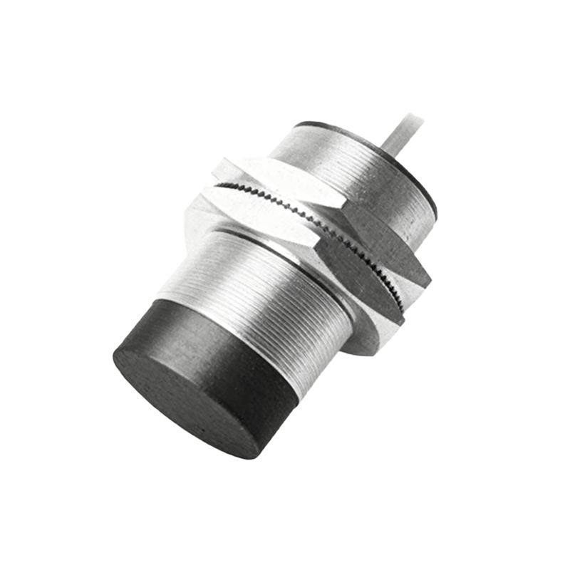
For example, in a PNP sensor setup:
- Brown wire: +V (positive supply)
- Blue wire: 0V (ground)
- Black wire: output signal to the load, with the load's other side connected to ground.
In an NPN sensor setup:
- Brown wire: +V (positive supply)
- Blue wire: 0V (ground)
- Black wire: output signal to the load, with the load's other side connected to +V.
Shielded cables are recommended for environments with electrical noise, such as factories with motors or frequency drives. Connect the cable shield to ground at one end only to avoid ground loops. Ensure wires are securely fastened and insulated to prevent short circuits.
After wiring, verify the connections. Use a multimeter to check voltage levels and continuity. Power on the system and test the sensor by placing an object within its detection range. The output LED should activate, and the load should respond accordingly. If issues arise, recheck wiring against the datasheet and confirm power supply stability.
Consider environmental factors. Laser proximity sensors may require additional protection in harsh conditions, such as conduit or enclosures for dust and moisture resistance. Follow local electrical codes and manufacturer guidelines for installation distances and mounting.
Regular maintenance includes inspecting wires for wear, cleaning the lens, and testing performance periodically. Proper wiring not only ensures functionality but also enhances system safety and efficiency. By adhering to these steps, you can integrate laser proximity sensors seamlessly into your automation projects, leveraging their high accuracy and fast response times for optimal results.
In summary, wiring a laser proximity sensor involves understanding its type, making correct power and output connections, and verifying operation. Attention to detail during installation minimizes errors and supports long-term reliability in industrial settings.