Introduction to Photoelectric Sensor Fundamentals
Photoelectric sensors are ubiquitous in modern industrial automation, serving as the eyes of a control system. Their primary function is to detect the presence, absence, or distance of an object using a light transmitter and receiver. The operating state of a photoelectric sensor is a critical parameter that determines its reliability and effectiveness within a circuit or network. This state is not merely "on" or "off" but encompasses a spectrum of conditions including normal detection, standby, alarm, and error modes. Understanding these states is paramount for system design, troubleshooting, and ensuring optimal performance in applications ranging from packaging and material handling to automotive assembly and safety systems.
Core Components and Light Beam Types

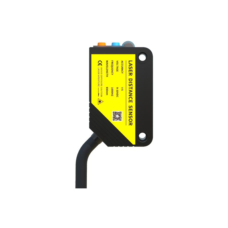
To comprehend operating states, one must first understand the sensor's architecture. All photoelectric sensors consist of a light source (typically an LED emitting visible red, infrared, or laser light), a receiver (a phototransistor or photodiode), and supporting electronics for signal processing. The configuration of these components defines the sensing mode: through-beam, retro-reflective, or diffuse. A through-beam sensor, with separate emitter and receiver units, provides the longest sensing range and highest reliability. A retro-reflective sensor uses a single unit and a reflector, while a diffuse sensor detects light reflected directly from the target object itself. Each type interacts with its environment differently, directly influencing its potential operating states and susceptibility to external factors like ambient light or target surface characteristics.
Defining Key Operating States
The operating state of a photoelectric sensor is the real-time condition of its output signal in relation to its detection logic and internal health. The primary states are:
1. Output Active (Light Operate/Dark Operate): This is the normal detection state. In "Light Operate" mode, the output switches ON when the receiver detects the light beam. In "Dark Operate" mode, the output switches ON when the beam is blocked. The chosen logic depends on the application's fail-safe requirements.
2. Output Inactive (Standby): This is the complementary state to Output Active. The sensor is powered and functional but its output is in the resting, non-triggered state.
3. Stable Detection vs. Flutter: A stable operating state indicates consistent, bounce-free switching. "Flutter" or a chattering state occurs when the output rapidly cycles between active and inactive. This is often caused by a vibrating target, unstable power supply, or detection at the very edge of the sensor's sensing window, requiring immediate attention to prevent downstream equipment errors.
Diagnostic and Error States
Modern photoelectric sensors incorporate sophisticated self-diagnostic capabilities, reporting their health through various indicators. Key diagnostic states include:
* Power/Stability Indicator (Green LED): A steady glow typically indicates proper power and normal operation. A blinking pattern may signal a specific condition, such as a teach-in mode for setting sensitivity.
* Output/Detection Indicator (Orange or Yellow LED): Illuminates when the output is active, providing visual confirmation of the target detection state.
* Alarm/Error State (Red LED or specific blink code): This critical state indicates a problem. Common triggers include a heavily contaminated lens (in both emitter and receiver for through-beam types), persistent ambient light interference exceeding the sensor's compensation range, a malfunctioning component, or a wiring fault. Some advanced sensors with IO-Link or other digital communication protocols can transmit detailed error codes (e.g., "Receiver Saturation," "Emitter Fault," "Short Circuit") directly to the controller for precise diagnostics.
Factors Influencing Sensor State Stability
Several external and internal factors can cause undesirable transitions between operating states. Ambient light from sunlight or high-intensity factory lamps can flood the receiver, causing a false "beam received" state. Dust, oil, or condensation on the lens attenuates the light signal, potentially leading to a missed detection or triggering an alarm state. Electrical noise from motors or variable frequency drives can induce signal noise, causing flutter. Furthermore, an inappropriate sensing mode for the application—such as using a diffuse sensor on a shiny, reflective target—will result in unreliable state switching. Proper mounting, alignment, and environmental protection are essential for maintaining a stable, intended operating state.
Best Practices for State Monitoring and Maintenance
Proactive monitoring of a photoelectric sensor's operating state is a cornerstone of predictive maintenance. Engineers should establish baseline behaviors during commissioning, noting the typical response time and LED indicators during normal cycles. Regularly inspect lenses for cleanliness and check for physical misalignment. Utilize sensors with built-in diagnostic outputs that can be wired into the PLC to provide early warnings of deteriorating conditions, such as a gradually declining received light intensity. Implementing a network of smart sensors allows for centralized monitoring of operating states across an entire production line, enabling maintenance teams to address issues before they cause unplanned downtime. Understanding and respecting the sensor's specified operating voltage, temperature range, and protection rating (IP67, etc.) is fundamental to ensuring long-term state reliability.
Conclusion and Integration with Control Systems
The operating state of a photoelectric sensor is a dynamic and informative signal. It goes beyond a simple binary switch to convey system health, detection confidence, and potential failure modes. By thoroughly understanding the definitions and causes of each state—from normal active/inactive cycles to diagnostic alarms—engineers can design more robust systems, write more intelligent control logic, and implement effective maintenance strategies. In the era of Industry 4.0, the ability to interpret and act upon these states digitally is key to achieving higher levels of automation efficiency, quality control, and overall equipment effectiveness (OEE).