Understanding Inductive Proximity Sensors
Inductive proximity switches are fundamental components in industrial automation, renowned for their non-contact detection of metallic objects. Operating on the principle of electromagnetic induction, these sensors generate an oscillating electromagnetic field from a coil within their sensing face. When a conductive metal target enters this field, eddy currents are induced on the target's surface. This causes a change in the oscillation amplitude or frequency within the sensor's internal circuit. The sensor's evaluation electronics detects this change and triggers a solid-state switching output. This robust operating principle makes them ideal for harsh environments where dirt, oil, or vibration are present, as they have no moving mechanical parts to wear out. Their reliability and long service life are key reasons for their widespread adoption in manufacturing, packaging, and material handling systems.
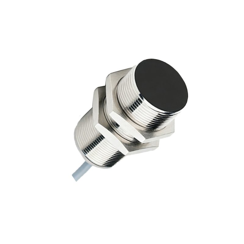
Core Wiring Configurations: 2-Wire, 3-Wire, and 4-Wire
The wiring methodology for an inductive proximity sensor is primarily defined by its number of connecting leads. The 2-wire sensor is the simplest type, connecting directly in series with the load, similar to a mechanical switch. It is cost-effective but has a higher residual current and voltage drop when "on," which can be a limitation for some control inputs. The 3-wire sensor is the most common configuration in industrial settings. It features separate wires for power supply positive (brown), power supply negative/ground (blue), and the switched output signal (black). This design allows for either a sinking (NPN) or sourcing (PNP) output transistor, providing clear compatibility with different PLC input modules. The 4-wire sensor typically incorporates two separate output channels, often one NPN and one PNP, or a normally-open and normally-closed pair, offering greater flexibility for complex control logic within a single device housing.
Detailed Analysis of 3-Wire Sinking (NPN) and Sourcing (PNP) Circuits
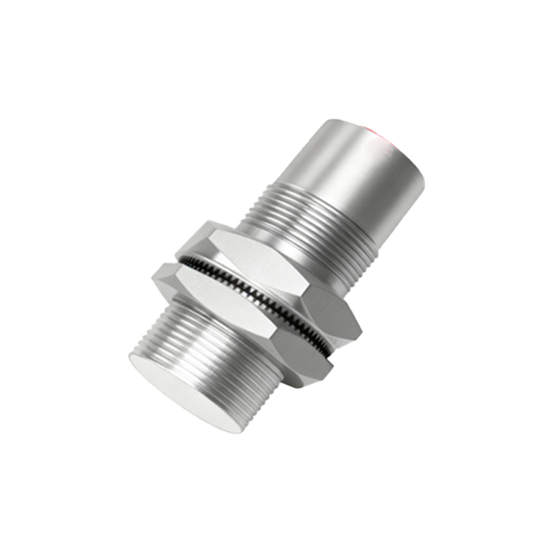
The distinction between sinking (NPN) and sourcing (PNP) wiring is critical for proper system integration. In a 3-wire PNP (sourcing) configuration, the sensor's output transistor is connected between the positive supply and the load. When activated, it sources current from the positive supply to the load. The load's other side is connected to the negative common. This is often summarized as "PNP = Positive Switched." Conversely, in a 3-wire NPN (sinking) configuration, the output transistor is connected between the load and the negative supply. When activated, it sinks current from the load to the negative common. The load's other side is connected to positive. This is summarized as "NPN = Negative Switched." Choosing between PNP and NPN is not about performance but about compatibility with the controller's input card. European designs frequently use PNP, while Asian and North American designs historically favored NPN, though both are now globally available.
Wiring Practices and Installation Considerations
Correct installation is paramount for reliable operation. Always refer to the manufacturer's datasheet for the specific wiring diagram, voltage ratings, and output current limits. Use shielded cables in electrically noisy environments, grounding the shield at the controller end only to prevent ground loops. Maintain the specified sensing distance and ensure the target metal type and size meet the sensor's specifications, as different metals (steel, aluminum, brass) have different correction factors. Avoid mounting sensors directly facing each other, as mutual interference can occur. Provide adequate mechanical protection from physical impact. For DC sensors, strict polarity observance is mandatory to prevent damage. It is also good practice to include a protective fuse or circuit breaker in the supply line and to use suppression diodes or RC networks when driving inductive loads like relays or solenoids to protect the sensor's output transistor from voltage spikes.
Troubleshooting Common Wiring and Operational Issues
Systematic troubleshooting begins with verifying the power supply voltage at the sensor terminals under load. A sensor that is permanently "on" may indicate incorrect wiring (e.g., a sourcing sensor connected to a sinking input), a short circuit in the cable, or a target that is too close or too large. A sensor that is never "on" could point to a wiring fault (open circuit, reversed polarity), an insufficient power supply, a damaged sensor, or an incompatible target (non-metallic or wrong metal type). Intermittent operation often suggests loose connections, electrical noise interference, or a target that is moving too fast for the sensor's response frequency. Using a multimeter to check voltage levels and continuity, along with an oscilloscope to inspect signal integrity in noisy settings, are standard diagnostic procedures for an electrical engineer.