Understanding Switching Outputs in Photoelectric Sensors
A photoelectric sensor's primary function is to detect the presence, absence, or distance of an object using a light beam. The core of its utility in control systems lies in its output stage, which translates the detection event into an electrical signal that programmable logic controllers (PLCs), relays, or other devices can understand. This output is typically a switching signal, a clean, decisive transition between two states: ON and OFF. Unlike analog outputs that provide a continuous range of values, a switching output provides a binary decision, making it ideal for straightforward tasks like counting, positioning, or initiating an action. The reliability and speed of this switching function are critical parameters in high-speed automation environments where milliseconds matter.
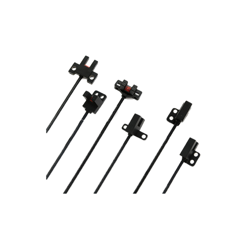
Common Types of Switching Outputs
Photoelectric sensors are available with several standard switching output configurations to match different control voltage levels and load types. The most prevalent are DC-powered sensors with transistor outputs. These are further divided into NPN (sinking) and PNP (sourcing) outputs. An NPN output switches the negative side (0V) of the load to the common negative, while a PNP output switches the positive side (+V) of the load to the common positive. Selecting the correct type is essential for compatibility with the input card of the controller. For AC line-voltage applications or controlling heavier loads like solenoids or contactors directly, sensors with electromechanical relay outputs are common. Relay outputs provide physical isolation between the sensor circuit and the load circuit, allowing control of high-voltage AC loads with a low-voltage DC sensor.
Output Operating Modes: Light-On vs. Dark-On
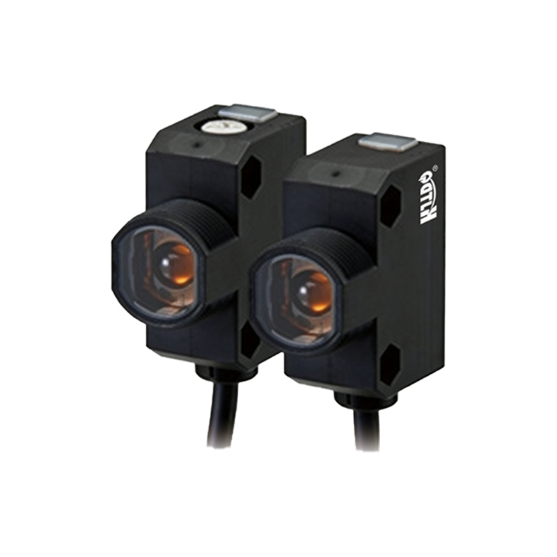
A fundamental configuration for any photoelectric sensor is defining its output logic, determined by the "operating mode." In Light-On mode (also called Light-Operate), the sensor's output switch turns ON (closes) when the receiver detects sufficient light from the transmitter. This mode is typically used in retro-reflective or through-beam sensors when no object is interrupting the beam. Conversely, Dark-On mode (Dark-Operate) activates the output switch when the light beam is blocked or sufficiently attenuated. The choice depends entirely on the application's logic; for instance, a Dark-On mode is intuitive for detecting an object on a conveyor, as the object's presence blocks the beam and triggers the output. Most modern sensors allow this mode to be easily selected via a switch or programming.
Key Electrical Specifications of Switching Outputs
When integrating a sensor into a system, engineers must carefully review the electrical specifications of its switching output. The load voltage range specifies the DC or AC voltage the output can switch. The maximum load current indicates how much current the output transistor or relay can safely handle continuously, crucial for preventing damage. The residual voltage or voltage drop across the output in the ON state is important in low-voltage logic circuits. Switching speed, often measured in milliseconds or microseconds, defines how quickly the output can change state after a detection event, a vital factor in high-speed counting or packaging lines. Additionally, protection features like short-circuit protection, reverse polarity protection, and surge suppression enhance durability in harsh industrial environments.
Wiring and Connection Considerations
Proper wiring is critical for reliable operation. A typical three-wire DC sensor has connections for power positive (brown), power negative (blue), and the switching output wire (black for NPN/PNP). For a four-wire device, a second complementary output is often provided. It is imperative to connect the load (e.g., a PLC input) correctly in series with the output switch. For an NPN sensor, the load is connected between the output wire and the positive supply; for a PNP, between the output wire and the negative supply. Shielded cables are recommended for long runs or electrically noisy environments to prevent electromagnetic interference from causing false triggering. Always adhere to the manufacturer's wiring diagrams and local electrical codes.
Application Examples in Automation Systems
The simplicity and reliability of switching outputs make photoelectric sensors ubiquitous. In material handling, through-beam sensors with Dark-On outputs detect boxes on a conveyor to control sorting gates or provide count signals to a PLC. In packaging machinery, diffuse sensors verify the presence of a product in a blister pack before the sealing cycle initiates. Retro-reflective sensors with Light-On logic are often used as safety curtain monitors on automated guided vehicles (AGVs), where the breaking of the beam indicates an obstacle and triggers an emergency stop. In assembly stations, precise polarized retro-reflective sensors detect small component orientation, with their output signaling a robot to pick or place a part.
Troubleshooting Output-Related Issues
Common issues often trace back to the output stage or its configuration. If a sensor's indicator light activates but the output does not switch, verify the load compatibility (voltage, current, NPN/PNP type) and check for wiring errors or a blown fuse. An output that seems "stuck" ON might be due to a wiring short or a sensor stuck in its operating mode (e.g., permanently light or dark). Inconsistent switching can result from electrical noise, insufficient power supply stability, or the load current being very close to the output's maximum rating, causing overheating. Always use a multimeter to measure the output voltage relative to the common terminal to confirm the switching action is occurring as expected under load.