Understanding the G6 Photoelectric Sensor
The G6 series photoelectric sensor is a versatile and robust component widely used in industrial automation for tasks such as object detection, counting, and positioning. Its operation is based on the principle of emitting a light beam—typically infrared, red, or laser—and detecting changes in the received light. These changes are triggered by the presence, absence, or specific characteristics of a target object. Before any adjustment procedure, it is crucial to understand the specific model's sensing mode: through-beam, retro-reflective, or diffuse reflective. Each mode has distinct alignment and setup requirements. Familiarize yourself with the sensor's datasheet, noting its sensing range, light source type, output configuration (NPN/PNP), and response time. A solid foundational understanding ensures that subsequent adjustments are performed correctly and safely, preventing operational failures or damage to the equipment.
Pre-Adjustment Safety and Preparation
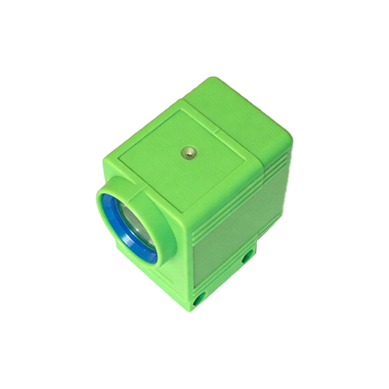
Safety is paramount when working with industrial sensors. Always begin by disconnecting the electrical power to the sensor and the associated machinery. Lock out and tag out (LOTO) the power source to prevent accidental re-energization. Ensure the work area is clean, well-lit, and free from obstructions. Gather the necessary tools, which typically include a small flat-head or Phillips screwdriver for potentiometer adjustments, the sensor's mounting hardware, and a non-metallic alignment tool if provided by the manufacturer. If available, refer to the specific adjustment manual for your G6 model. Visually inspect the sensor lens for dust, oil, or debris, and clean it gently with a soft, lint-free cloth if necessary. A dirty lens is a common cause of poor performance and false triggering.
Mechanical Alignment and Mounting
Correct mechanical mounting is the first critical step in sensor adjustment. For through-beam sensors, securely mount the emitter and receiver units opposite each other. They must be positioned so that their optical axes are perfectly aligned. Use a spirit level or alignment gauge if precision is required. For retro-reflective sensors, ensure the reflector is mounted squarely to the sensor's beam. The reflector should be clean and undamaged. Diffuse sensors must be mounted at an appropriate distance and angle relative to the target. Avoid mounting the sensor on surfaces that vibrate excessively, as this can lead to misalignment over time. Tighten all mounting hardware firmly, but avoid over-torquing, which could distort the sensor housing. Proper mechanical setup minimizes the need for extensive electronic sensitivity adjustments later.
Electrical Wiring and Power Connection
After secure mounting, proceed with electrical connections according to the wiring diagram provided in the sensor's manual. Connect the correct voltage supply (commonly 10-30V DC) to the designated terminals, observing polarity. Connect the load (e.g., a PLC input, relay, or indicator) to the output terminal. Double-check that the wiring matches the sensor's output type (sourcing/NPN or sinking/PNP) to avoid damaging the sensor or the controller. Once wiring is confirmed, restore power. Most G6 sensors have a stable power indicator LED (often green) and a separate output or signal indicator LED (often orange or red). The power LED should illuminate steadily, confirming correct voltage supply. If it does not light, immediately disconnect power and re-check your connections.
Adjusting Sensitivity and Setting the Threshold
The core of photoelectric sensor adjustment lies in setting the correct sensitivity threshold. This is typically done using a potentiometer accessible through a small hole in the sensor housing. The goal is to distinguish reliably between the "object present" and "object absent" states. With a representative target object in position, slowly rotate the sensitivity potentiometer. Observe the output indicator LED. For a diffuse sensor, place the target at the desired sensing distance. Adjust the potentiometer until the output LED just turns on when the target is present and just turns off when it is removed. This point is the optimal threshold. For through-beam and retro-reflective modes, ensure the beam is unbroken (receiver sees light) for the "no object" state. The adjustment process is similar: fine-tune until the output state changes cleanly with object interruption. Avoid setting the sensitivity excessively high, as this can cause instability due to background reflections or dust.
Fine-Tuning with Response Time and Function Switches
Advanced G6 models may feature additional adjustment switches or potentiometers for response time, operating mode (light-on/dark-on), and output timing functions. The response time setting controls how quickly the sensor reacts to a change in state. For high-speed applications, set a fast response time. For environments with vibration or slowly moving objects, a longer response time can help filter out noise and prevent chatter. The light-on/dark-on switch defines the logic of the output. "Light-on" means the output is active when the receiver detects the light beam (common in through-beam). "Dark-on" means the output activates when the beam is blocked. Select the mode that integrates correctly with your control system logic. Use any timing functions (like on-delay or off-delay) if your application requires a sustained signal after detection.
Verification and Testing Under Operational Conditions
After completing all adjustments, a thorough verification phase is essential. Do not rely on a single test. Introduce the target object repeatedly at varying speeds and positions within the intended sensing window. Test edge cases: use objects at the minimum and maximum specified sensing distance, and test with objects of different colors or surface finishes if applicable. Observe the sensor's output indicator and, if possible, monitor the actual signal at the PLC or controller. The sensor should trigger consistently without missed detections or false positives. If the environment contains ambient light interference (like welding arcs or sunlight), test under those conditions and re-adjust sensitivity if necessary. For critical applications, run a prolonged test cycle, simulating normal production for at least 15-30 minutes to ensure long-term stability.
Troubleshooting Common Adjustment Issues
Even with careful adjustment, issues may arise. If the sensor does not trigger, verify power, wiring, and alignment. Check for obstructions in the beam path. If the output chatters or flickers, the sensitivity is likely set too high. Reduce sensitivity slightly. For diffuse sensors, a glossy target might reflect light inconsistently; try adjusting the sensor angle. If sensing distance is shorter than specified, clean the lens and ensure the target has adequate reflectivity or opacity. Electrical noise can also cause erratic behavior; ensure cables are shielded and routed away from power lines or motor drives. Consult the sensor's manual for specific error code interpretations if the unit has diagnostic indicators. Persistent problems may indicate a faulty sensor, damaged lens, or incompatible environmental conditions.
Maintenance and Periodic Re-calibration
To ensure continued reliable operation, integrate G6 sensor checks into your preventative maintenance schedule. Periodically inspect the lens for contamination and clean it. Check mounting hardware for tightness, as vibration can loosen fixtures. Verify alignment, especially in applications with thermal expansion or mechanical stress. Re-test the sensitivity threshold every six