Understanding Photoelectric Sensor Indicator Lights
Photoelectric sensors are essential components in industrial automation, providing reliable object detection through various sensing methods. A key feature of these sensors is their indicator lights, which offer immediate visual feedback on operational status. Typically, modern photoelectric sensors are equipped with multiple LED indicators, each serving a distinct purpose. The most common lights include a power indicator, a stability or output indicator, and sometimes a teach or alignment indicator. Recognizing what each light signifies during normal operation is crucial for proper installation, troubleshooting, and ensuring system reliability. This knowledge helps operators and maintenance personnel quickly verify sensor health and functionality without needing to consult manuals or use diagnostic tools for basic checks.
Standard Power Indicator Light Behavior
The power indicator light, often labeled as "PWR" or simply represented by a steady green LED, is the primary sign of sensor vitality. Under normal operating conditions, this light should be illuminated continuously when the sensor is correctly connected to its power supply, which is typically within a range of 10-30V DC or 20-250V AC, depending on the model. A solid, unwavering green light confirms that the sensor is receiving adequate voltage and is internally powered on. Some advanced models might use a different color, such as blue, for power, but green remains the industry standard. If this light is off, it indicates a lack of power, incorrect wiring, or a potential internal fault. A flickering power light often points to unstable voltage supply or wiring issues.
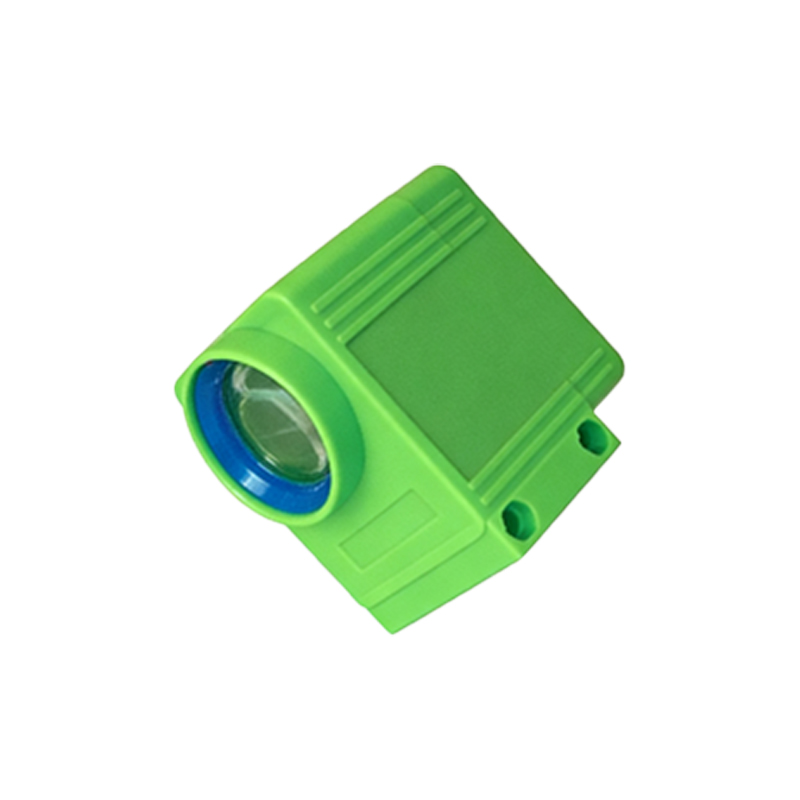
Normal Output and Stability Indicator Status
The output or stability indicator, frequently an orange or yellow LED, provides direct insight into the sensor's detection state. In a normally operating diffuse, retro-reflective, or through-beam sensor, this light's behavior is tied to the presence or absence of the target object. When no object is within the sensing range, the light is typically off, and the sensor's output transistor is in its default state (often open or closed, depending on the configuration—light-on or dark-on). When a valid object is detected, this indicator light will turn on solidly, signaling that the output has switched. For sensors with a stability function, a slow blinking pattern might indicate optimal alignment and stable detection conditions, assuring the user that the sensor is not on the verge of losing the signal due to marginal conditions.
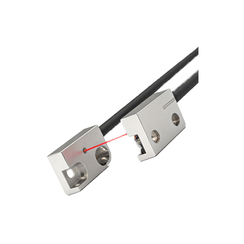
Alignment and Teach Mode Indicators
Many photoelectric sensors feature a dedicated alignment aid or teach mode indicator, usually a red LED. During the initial setup or alignment process, this light provides critical feedback. In normal operation—after successful alignment—this light is typically off. However, when you activate the alignment mode (often by pressing a button or applying a specific sequence), this red LED will illuminate or blink. A common pattern is a rapid blink when the received light signal is weak or absent, transitioning to a slow blink as alignment improves, and finally turning off or showing a solid light when optimal alignment is achieved. This process is vital for through-beam and retro-reflective sensors where precise optical alignment is necessary for reliable operation.
Special Function Indicators and Their Meanings
Advanced photoelectric sensors may include additional indicators for special functions like short-circuit protection, overload warning, or communication status (for IO-Link or network-enabled sensors). Under normal conditions, these specialized indicators should remain off. For instance, a sensor with built-in short-circuit protection might have a specific LED that only flashes if an output short is detected. Similarly, an IO-Link sensor might have a dedicated LED that blinks in a specific pattern to indicate successful data exchange or a steady light to show a stable communication link. Understanding the manual for your specific model is key, as the color and blink patterns for these advanced functions are not standardized across all manufacturers.
Interpreting Blink Patterns for Diagnostics
While solid lights indicate normal states, deliberate blink patterns are a form of built-in diagnostic communication. A sensor operating normally with no faults will not have any unexpected blinking from its power or output indicators. However, a controlled, periodic blink from the output LED might be a programmable feature to indicate standby or a specific operating mode. Manufacturers often design specific error codes communicated through blink sequences (e.g., two short blinks followed by a pause) for conditions like contaminated lens, temperature out of range, or internal error. In a normal, healthy state, these error blink codes are absent. Familiarity with these patterns allows for quick differentiation between a normal status indication and an early warning of a developing issue.
Ensuring Optimal Performance Through Observation
Regular visual inspection of a photoelectric sensor's indicator lights is a simple yet powerful predictive maintenance tool. A normal state is characterized by a steady green power light and an output light that responds consistently to the presence or absence of targets. The alignment light should be off during standard runtime. Any deviation from this—such as dimming, flickering, or unexpected activation of any indicator—warrants investigation. Environmental factors like excessive ambient light, dust accumulation on the lens, or electrical noise can sometimes cause subtle changes in indicator behavior even before a detection failure occurs. By knowing the normal "light language," technicians can ensure sensors continue to contribute to efficient, uninterrupted automation processes.