Introduction to Proximity Sensing Technology
Proximity sensors are fundamental components in modern industrial automation, providing non-contact detection of metallic and, in some cases, non-metallic objects. Among the various configurations available, the 3-wire DC normally open (NO) sensor is one of the most prevalent and reliable designs used in control systems worldwide. These sensors operate by generating an electromagnetic field and detecting changes caused by a target object entering this field. The 3-wire design specifically refers to the wiring configuration: one wire for power supply (typically +V DC), one wire for the ground or common (0V), and one wire for the switched output signal. The "normally open" designation indicates that in the absence of a target, the output switch is open, meaning no current flows through the output circuit. When a target enters the sensor's sensing range, the internal electronic switch closes, completing the circuit and allowing current to flow to the connected load, such as a PLC input, relay, or indicator lamp.
Internal Circuitry and Operating Principle
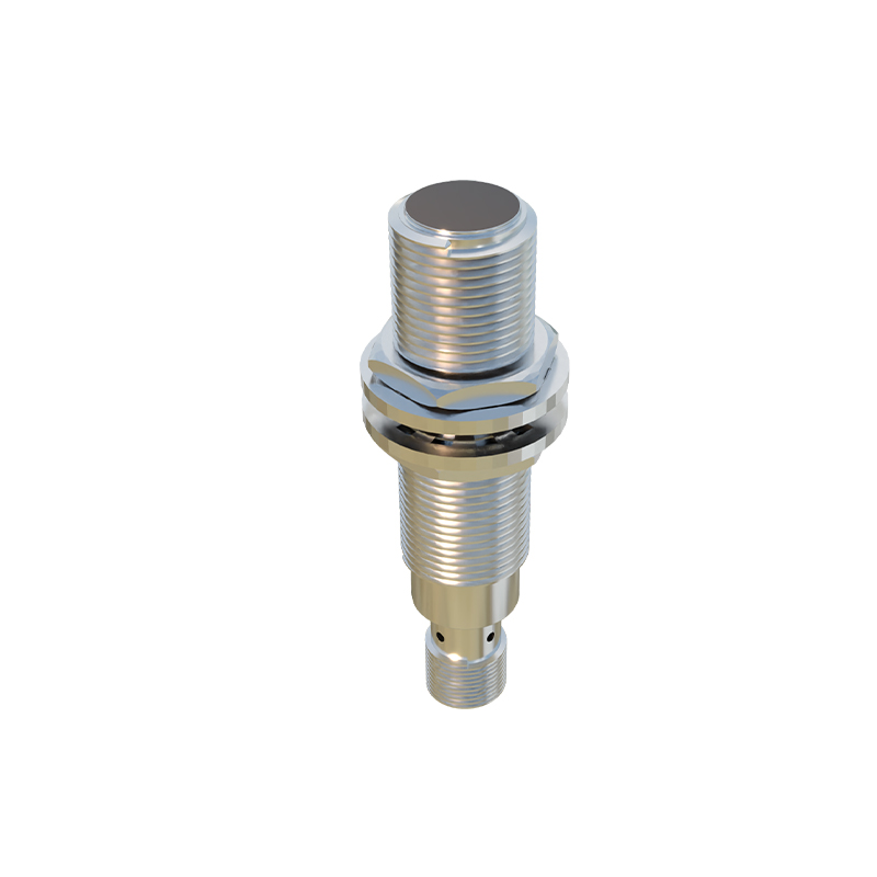
The core of a 3-wire NO proximity sensor is an oscillator circuit that generates a high-frequency electromagnetic field at the sensing face. This field is emitted by a coil. When a conductive target (like steel, aluminum, or brass) approaches this field, eddy currents are induced on the target's surface. These eddy currents draw energy from the oscillator, causing its amplitude to decrease. A detection circuit monitors this amplitude change. Once the amplitude drops below a predetermined threshold—corresponding to the target being within the specified sensing distance—the circuit triggers a solid-state output switch. For a normally open PNP sensor (sourcing), the output wire switches to connect to the positive supply voltage. For a normally open NPN sensor (sinking), the output wire switches to connect to the ground/common. This switching action is performed by a transistor (hence the 3-wire design), providing a fast, bounce-free signal ideal for high-speed counting and positioning applications.
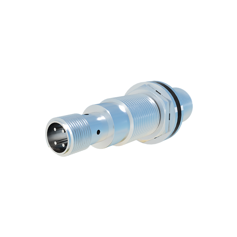
Wiring Configurations and Electrical Characteristics
Correct wiring is critical for safe and reliable operation. The three wires are usually color-coded: brown for +V DC (power), blue for 0V (common/ground), and black for the switched output signal. It is paramount to verify the sensor's datasheet, as some manufacturers may use different color standards. The operating voltage range is typically between 10-30V DC, with 24V DC being the industrial standard. The output current rating, often between 100-300 mA, must not be exceeded to prevent damage to the internal switching transistor. A key advantage of the 3-wire design is that it allows for a common 0V reference between the sensor, the power supply, and the load, simplifying system design. When wiring, ensure the load (e.g., a PLC digital input) is connected between the output wire (black) and the opposite potential: for a PNP sensor, the load connects between black and blue (0V); for an NPN sensor, the load connects between black and brown (+V).
Key Selection Criteria for Application
Selecting the appropriate 3-wire NO proximity sensor requires careful consideration of several application parameters. First, determine the sensing distance required, noting that the rated operating distance is specified for a standard mild steel target. For other metals, a correction factor must be applied. Second, choose the correct housing material (e.g., nickel-plated brass, stainless steel) and shape (cylindrical, rectangular, ring-shaped) based on the mechanical and environmental constraints. Third, the output type (PNP vs. NPN) must match the control system's input card configuration. Fourth, consider switching frequency; high-speed models are available for rapid assembly lines. Finally, environmental factors are crucial. Many sensors feature IP67 or IP69K ratings for protection against dust and water ingress, and some are specifically designed to withstand extreme temperatures, cutting fluids, or weld-field immunity in robotic welding cells.
Installation Best Practices and Troubleshooting
Proper installation maximizes sensor performance and longevity. Maintain the recommended clearance around the sensor body, especially between the sensing face and the mounting nut, to prevent false triggers from the metal mount itself. Avoid mounting multiple sensors directly opposite each other, as their alternating fields can cause mutual interference; staggering them or using sensors with anti-interference technology is advised. For troubleshooting, a systematic approach is best. If a sensor fails to operate, first check the power supply voltage at the sensor's terminals. Next, verify the wiring against the datasheet diagram. Use a multimeter to measure the output voltage: in the absence of a target