Understanding Rectangular Proximity Sensor Fundamentals
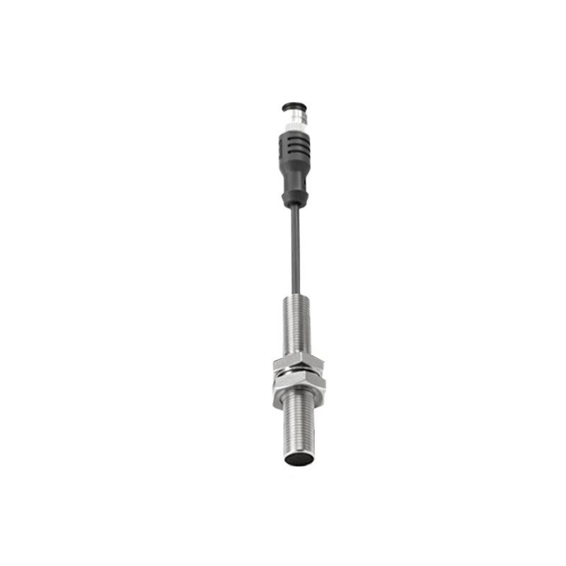
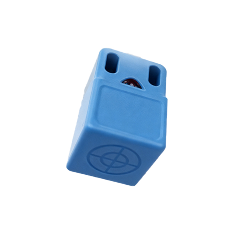
Rectangular proximity sensors are indispensable components in modern industrial automation, designed to detect the presence or absence of an object without physical contact. These robust sensors, typically housed in a durable rectangular metal or polymer casing, operate on principles such as inductive, capacitive, or ultrasonic sensing. Inductive sensors are most common for metal detection, while capacitive types can sense a wider range of materials including liquids and plastics. Before initiating any wiring procedure, it is paramount to consult the specific sensor's datasheet. This document provides critical information regarding the sensor's type (PNP or NPN, normally open or normally closed), operating voltage range (commonly 10-30V DC), current rating, and output configuration. A clear understanding of these specifications is the foundation for a safe and correct installation.
Essential Tools and Safety Precautions
Gathering the correct tools and adhering to safety protocols is non-negotiable. You will typically need a screwdriver set, wire strippers, crimping tools, appropriate gauge electrical wires (often shielded cable for noise immunity), and possibly a multimeter for verification. Prior to any work, ensure the complete lockout/tagout (LOTO) of the power supply to the control circuit. Verify that the voltage is off using a multimeter. Always follow local and national electrical codes and standards, such as NEC or IEC regulations. Personal protective equipment (PPE) like safety glasses and insulated gloves should be worn. Remember, incorrect wiring can lead to sensor failure, damage to connected equipment like PLCs, or create serious safety hazards.
Deciphering the Connection Diagram and Terminal Designations
Every rectangular proximity sensor features a connection diagram, usually printed on its body or detailed in the manual. Standard color-coding and terminal markings are used across the industry. For a typical 3-wire DC sensor, you will find:
- Brown wire (or terminal marked +V, L+): This is the positive power supply lead. Connect it to the positive terminal of your DC power source (e.g., 24V DC).
- Blue wire (or terminal marked 0V, L-, N): This is the negative power supply lead or common. Connect it to the negative terminal of the DC power source.
- Black wire (or terminal marked OUT, Q, or signal): This is the switched output lead. The state of this wire (energized or de-energized) changes based on target detection.
Some sensors may have an additional white wire for a complementary output or diagnostic function. For 2-wire AC/DC sensors, the wiring is simpler, with two terminals that connect in series with the load and power supply. Precise identification is crucial.
Step-by-Step Wiring Procedure for a 3-Wire DC Sensor
First, prepare the cables. Strip the insulation from the ends of your supply and load wires. If using a pre-made cable gland, feed the cable through the sensor's housing entry before stripping. For the power connection, connect the brown wire from the sensor to the positive (+) rail of your 24V DC power supply. Connect the blue wire from the sensor to the negative (-) rail or common of the same power supply. This provides the operating voltage to the sensor's internal circuitry. Next, for the output connection, connect the sensor's black output wire to the input terminal of your load device. This load is typically a programmable logic controller (PLC) input module, a relay coil, or an indicator lamp. Finally, connect the other side of that load device back to the negative (-) power supply rail, completing the circuit. Ensure all terminal screws are tightened securely to prevent loose connections, which are a common source of malfunction.
Configuring PNP vs. NPN Sinking and Sourcing Circuits
This is a critical conceptual step. The choice between PNP and NPN dictates how the output signal is referenced. A PNP sensor (sourcing) switches the positive voltage to the output wire. When active, its black wire provides positive voltage to the load. The load is then connected between the black wire and the negative supply. An NPN sensor (sinking) switches the negative or ground path. When active, its black wire provides a path to negative. Here, the load is connected between the positive supply and the black wire. Most PLC input cards are designed to work with either type but may require specific commoning of the DC commons. Mismatching sensor output type with the PLC input type will result in the signal not being read. Always verify compatibility.
Testing, Troubleshooting, and Final Installation
After wiring is complete and before fully securing