Understanding Two-Wire Proximity Sensor Fundamentals
Two-wire proximity sensors are widely used in industrial automation due to their simplicity and direct compatibility with programmable logic controller (PLC) input modules. Unlike three-wire sensors that have separate power, signal, and ground lines, two-wire sensors integrate the load (often the PLC input) directly into the same circuit loop as the power supply. They function as a switch that modulates current flow. When no target is detected, a small leakage current (typically under 2 mA) flows. Upon detecting a target within its sensing range, the sensor switches to a low-impedance state, allowing the operating current (usually between 5-20 mA, depending on the model and voltage) to flow, which the PLC interprets as an "ON" signal. This inherent current consumption is a critical factor when considering series connections.
The Principle and Challenge of Series Connection
Connecting two or more two-wire proximity sensors in series involves wiring them sequentially in a single loop, so the same current flows through each sensor before reaching the PLC input. The primary motivation is to reduce wiring complexity and the number of required PLC input channels by creating a logical "AND" function. The combined signal to the PLC will only be "ON" if all sensors in the series string are activated simultaneously. However, the main challenge is voltage drop. Each active sensor in the series has an internal voltage drop (often 2-5V). The sum of these drops, plus the voltage required by the PLC input to recognize an "ON" state (its "ON-state voltage"), must be less than the available power supply voltage. If the total voltage drop exceeds the supply, the current will be insufficient to reliably trigger the PLC input, causing intermittent or failed operation.
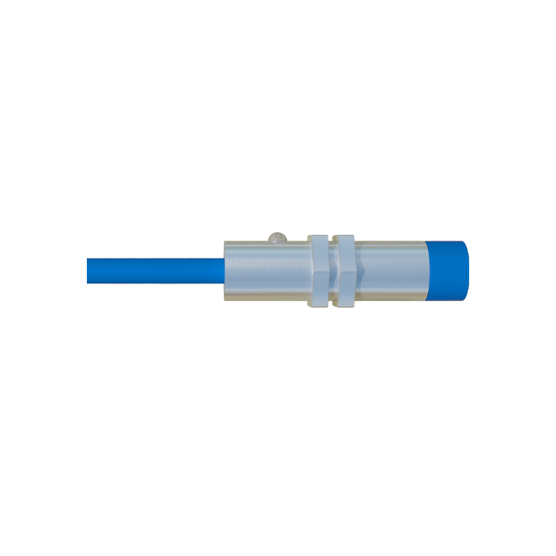
Key Calculations for a Reliable Series Circuit
Successful implementation requires careful electrical calculation. First, determine the supply voltage (Vs), commonly 24V DC. Next, ascertain the minimum current (I_min) required by your PLC's digital input to register an "ON" signal (consult the datasheet). Then, for each sensor model, identify its maximum voltage drop (V_drop) when conducting and its minimum operating current (I_op). The critical check is: Vs > (Sum of V_drop for all active sensors) + (PLC input ON-state voltage). The PLC input ON-state voltage is calculated as I_min R_input (input impedance). Furthermore, the power supply must deliver a current greater than the highest I_op of any sensor in the chain. Using sensors with low voltage drop characteristics is highly advantageous for series configurations. Always include a safety margin of 10-20% in your voltage calculations.
Practical Wiring and Configuration Guidelines
Begin by selecting sensors specifically rated for series connection or those with a very low voltage drop. Wire the brown (or +) wire of the first sensor to the positive terminal of the power supply. Connect the blue (or -) wire of the first sensor to the brown wire of the second sensor. Continue this daisy-chain pattern. Finally, connect the blue wire of the last sensor to the PLC input terminal, and connect the common terminal of that PLC input module to the negative side of the power supply. It is crucial to place a bypass or monitoring resistor in parallel with the PLC input if the total leakage current from all inactive sensors in the series exceeds the PLC's "OFF-state" current threshold, which could falsely trigger an input. Test the circuit with all sensors activated and measure the voltage at the PLC input to ensure it is within the specified "ON" range.
Common Applications and Logical Considerations
Series connections are ideal for safety or sequencing interlocks where multiple conditions must be met before an action proceeds. A classic example is a machine guard system: a series of door-position sensors on an enclosure must all indicate "door closed" (sensors activated) before the machine is allowed to start. Another application is in material handling, where sensors on consecutive stations must all confirm the presence of a workpiece before initiating a transfer cycle. It is vital to remember that the series creates an "AND" logic; the system cannot distinguish which sensor is off. For diagnostics, this can be a disadvantage. Therefore, series circuits are best used for functions where the identity of a tripped sensor is not individually required for the process logic.
Troubleshooting and Best Practices
If a series circuit fails to trigger the PLC input, measure the voltage at the input when all sensors are active. A low reading indicates excessive voltage drop. Solutions include: using a higher supply