Introduction to Photoelectric Sensor Fundamentals
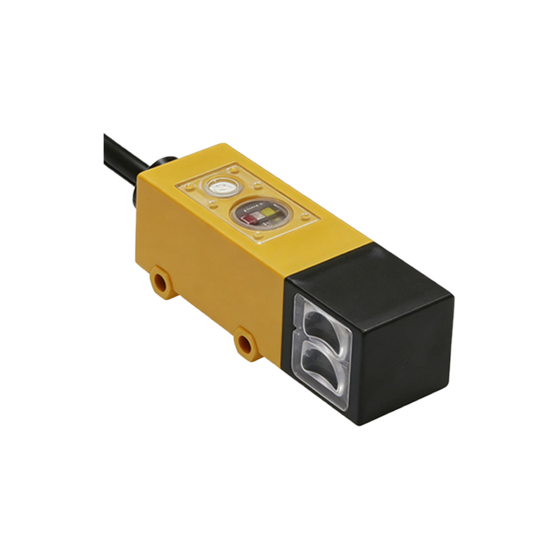
Photoelectric sensors are pivotal components in modern industrial automation, leveraging light beams to detect the presence, absence, or distance of objects. The core principle involves an emitter, typically an LED or laser diode, which projects light onto a target. A photodetector, such as a phototransistor or photodiode, then receives the reflected or transmitted light. Changes in the received light intensity are converted into electrical signals, enabling precise object detection. These sensors are renowned for their non-contact operation, high speed, and reliability across diverse environments, from manufacturing assembly lines to consumer electronics. Understanding the underlying electronic circuitry is essential for optimizing performance, ensuring stability, and tailoring designs to specific applications. This article delves into detailed circuit schematics, breaking down each functional block to provide a comprehensive guide for engineers and designers.
Core Circuit Blocks and Component Selection
The architecture of a photoelectric sensor circuit can be segmented into several key blocks: the emitter driver, the receiver amplifier, signal conditioning, and output interface. For the emitter, a constant current source circuit is often employed to drive the LED or laser diode. This ensures consistent light output, mitigating effects from power supply fluctuations or temperature variations. A simple implementation uses a bipolar junction transistor (BJT) or MOSFET in conjunction with a current-limiting resistor and operational amplifier for feedback control. For instance, an op-amp can regulate the voltage across a sense resistor, maintaining a fixed current through the emitter diode. Component selection here is critical; the LED's wavelength (e.g., infrared at 880nm for reduced ambient interference) and forward voltage must align with the driver's specifications to prevent premature degradation or insufficient illumination.
Receiver Section: Photodetector and Transimpedance Amplifier
On the receiver side, the photodetector converts incident light into a small photocurrent. Photodiodes are commonly used in photovoltaic or photoconductive modes. In most sensor designs, the photodiode operates in photoconductive mode with a reverse bias, enhancing response speed and linearity. The minute photocurrent (often in the nanoamp to microamp range) requires amplification. A transimpedance amplifier (TIA) is the preferred circuit for this task. It converts the current signal into a measurable voltage output. The TIA typically centers around a high-gain op-amp with a feedback resistor that sets the gain. Stability is paramount; a feedback capacitor is added to compensate for the photodiode's junction capacitance and prevent oscillations. Selecting an op-amp with low input bias current and low noise (e.g., JFET-input types) is crucial to maximize signal-to-noise ratio, especially in low-light conditions or for long-range detection.
Signal Conditioning and Threshold Detection
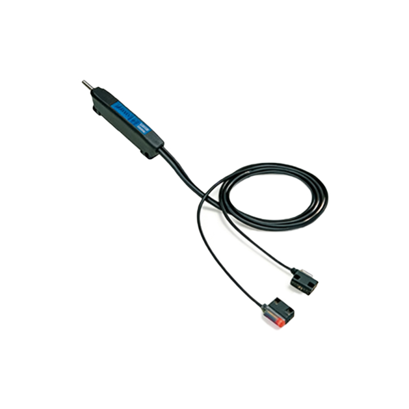
The raw voltage output from the TIA often contains noise and may need further conditioning. This stage typically involves filtering and comparison. A passive RC low-pass filter can attenuate high-frequency noise from ambient light sources or electrical interference. For more precise control, an active filter using an op-amp (e.g., a Sallen-Key configuration) can be implemented. Following filtering, a comparator circuit determines the sensor's state. A reference voltage, set by a voltage divider or potentiometer, establishes a detection threshold. When the conditioned signal voltage exceeds this threshold, the comparator's output switches state (e.g., from low to high), indicating object detection. Hysteresis, achieved by adding positive feedback with a resistor, is vital to prevent output chatter when the signal hovers near the threshold due to noise or slowly passing objects.
Output Interface and Power Management
The final stage involves interfacing the sensor with external systems like PLCs, microcontrollers, or actuators. Common output types include digital (NPN/PNP transistor open-collector), analog (0-10V or 4-20mA), or push-pull. An NPN output circuit, for example, uses a bipolar transistor to sink current to ground when active. Protection components like flyback diodes for inductive loads and current-limiting resistors are integrated here. Power management is another critical aspect. Many industrial sensors operate on a wide voltage range (e.g., 10-30V DC). A voltage regulator, such as a linear regulator or switching buck converter, provides stable low-voltage rails for the analog and digital circuitry. Decoupling capacitors placed near each IC power pin are essential to suppress noise and ensure reliable operation.
Practical Schematic Analysis and Layout Considerations
A complete schematic integrates all aforementioned blocks. Let's analyze a typical diffuse-reflective sensor schematic. The emitter driver might use a 555 timer in astable mode or a microcontroller-generated PWM signal to modulate the LED at a specific frequency (e.g., 5kHz). This modulation allows the receiver to distinguish the sensor's own light from ambient background light. The receiver TIA amplifies the signal, which then passes through a band-pass filter tuned to the modulation frequency. A demodulator (like a peak detector or synchronous demodulator) extracts the envelope. The comparator then triggers the output. PCB layout is as crucial as the circuit design. The emitter and receiver should be optically isolated to prevent crosstalk. Analog and digital grounds must be separated and joined at a single point to minimize noise coupling. Traces for sensitive analog signals should be short and shielded if necessary.
Conclusion and Design Optimization Tips
Designing a robust photoelectric sensor circuit requires careful attention to each subsystem. Start by defining key parameters: sensing range, response time, environmental conditions (dust, temperature), and output requirements. Simulate the TIA and filter stages using SPICE tools to verify stability and frequency response. For long-range or high-precision applications, consider using a lens to focus the light beam. Always prototype and test under real-world conditions, adjusting thresholds and filter cutoffs as needed. By mastering these circuit principles and adhering to sound layout practices, engineers can develop photoelectric sensors that deliver consistent, reliable performance in demanding automation and control systems.