Understanding Photoelectric Sensor Terminals
Photoelectric sensors are pivotal components in industrial automation, enabling non-contact detection of objects. The wiring terminal diagram serves as the essential blueprint for correct installation and operation. Typically, these sensors feature terminals for power supply, output signal, and sometimes auxiliary functions. Common terminal designations include V+ or +V for positive power supply, V- or COM for common/negative, and OUT for the output signal. Some advanced models may include terminals for teaching inputs (TEACH), timer functions, or diagnostic outputs. Misinterpreting these terminals can lead to sensor malfunction or damage to connected control systems like PLCs. Therefore, a thorough understanding of the specific terminal layout, as depicted in the manufacturer's diagram, is the foundational step before any wiring commences.
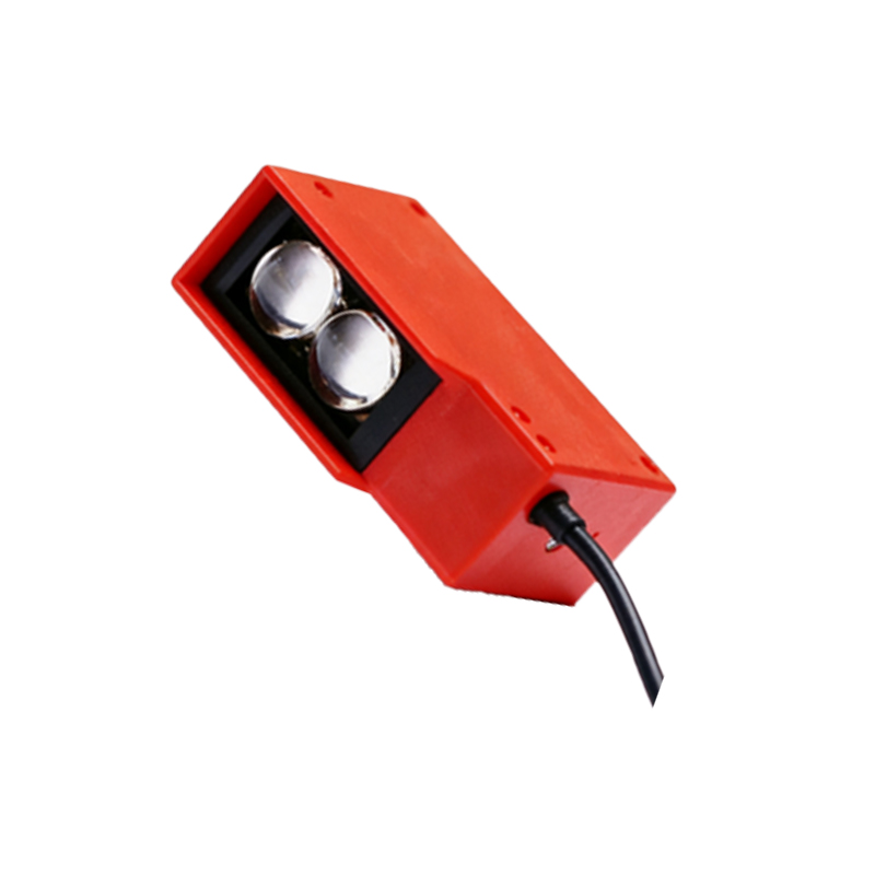
Standard Wiring Configurations
The wiring configuration is primarily determined by the sensor's output type. The two most prevalent types are NPN (sinking) and PNP (sourcing) outputs. For an NPN output sensor, the load (e.g., a PLC input) is connected between the V+ terminal and the OUT terminal. The output transistor switches the connection to V- (COM). Conversely, for a PNP output sensor, the load is connected between the OUT terminal and V- (COM), with the output transistor switching the connection to V+. The power supply terminals (e.g., 10-30V DC) are connected accordingly. Many sensors also feature a wire color code: brown for V+, blue for V- (COM), and black for the output signal. A clear terminal diagram will explicitly indicate the output type and the corresponding wiring path for the load circuit.
Interpreting the Terminal Diagram
A photoelectric sensor terminal diagram is more than just a list of connections. It is a symbolic representation of the sensor's internal electrical interface. The diagram usually presents a front or side view of the terminal block or connector pins. Each terminal point is labeled with its function abbreviation. Adjacent to these labels, you will often find critical electrical ratings such as maximum voltage, current capacity, and short-circuit protection details. For sensors with multiple operating modes (e.g., light-on/dark-on), the diagram may show how internal jumper settings or wiring to specific configuration terminals (like L.ON/D.ON) alter the logic of the output signal. Cross-referencing this diagram with the operation manual is crucial for configuring advanced features.
Wiring Practices for Reliability
Correct wiring ensures long-term reliability and prevents electrical noise interference. Always use the recommended wire gauge, typically between 0.2 to 2.5 mm², as specified in the manual. For long cable runs, use shielded cables and connect the shield to the ground terminal (if available) or to a stable earth ground point at the control panel, avoiding ground loops. Secure all connections tightly to prevent loosening from vibration. It is a best practice to implement separate conduits or cable trays for sensor power lines and high-current AC lines to minimize inductive coupling. Furthermore, incorporating protective devices like fuses or surge suppressors in the supply line, as sometimes indicated in application notes within the terminal diagram documentation, can safeguard the sensor from voltage spikes.
Troubleshooting Based on Terminal Points
When a photoelectric sensor fails, systematic troubleshooting starting from the terminal points is effective. First, verify the power supply voltage between V+ and V- terminals with a multimeter. If power is correct, check the output state. For a detecting sensor, the voltage between the OUT terminal and COM should switch (e.g., from 0V to ~V+ for PNP) when an object is presented. If there is no change, the issue may be with alignment, sensing mode, or the sensor itself. Some diagnostic sensors have a dedicated terminal (often labeled DIAG or ST) that provides a stability output or fault indication. Consulting the terminal diagram helps identify these special pins and understand their signaling, enabling faster isolation of wiring faults from application or component failures.
Advanced Features and Special Terminals
Modern photoelectric sensors incorporate functionalities that require additional terminals. These may include:
- Teach-in Terminal (TEACH/TCH): Allows programming of sensitivity or setpoints via an external button or controller signal.
- Timer Function Terminals (TM/T-OUT): Wiring to these enables on-delay or off-delay timing functions.
- Synchronization Input (SYNC): For preventing interference between multiple sensors by synchronizing their light emission pulses.
- Analog Output Terminals (AO/I-OUT): Provide a continuous current or voltage signal proportional to the received light intensity or distance.
- Dual Outputs (OUT1, OUT2): Independent outputs for separate thresholds or window comparator functions.
The terminal diagram is indispensable for implementing these features, showing how to connect external devices, set internal switches, or configure the terminals via software to activate the desired advanced operation mode.