Understanding Proximity Sensor Fundamentals
Proximity sensors are indispensable components in modern industrial automation, detecting the presence or absence of an object without physical contact. Their operation hinges on electromagnetic fields, capacitive changes, or ultrasonic waves. The core principle involves generating a sensing field; when a target object enters this field, it causes a detectable change in the sensor's output state. This non-contact nature makes them ideal for harsh environments, high-speed applications, and scenarios requiring high reliability and longevity. Selecting the correct sensor type—inductive, capacitive, or ultrasonic—is the foundational step before any adjustment process begins. Each type responds to different material properties and has unique installation and tuning requirements.
Key Components of Adjustment Mechanisms
The adjustability of a proximity sensor is crucial for precise operation. Primary adjustment mechanisms typically involve sensitivity controls and timing functions. A sensitivity potentiometer, often a small screw or dial, allows fine-tuning of the sensing range. This adjustment compensates for variations in target material, size, or environmental conditions like temperature and humidity. Some advanced models feature teach-in functions, where a button is pressed while presenting the target to automatically set the optimal sensing point. Additionally, built-in timers for on-delay, off-delay, or one-shot pulses are common adjustable parameters, enabling the sensor to integrate seamlessly with complex machine cycles and logic controllers.
Mechanical Mounting and Initial Alignment
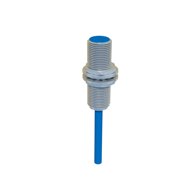
Proper mechanical installation is the first critical step in the debugging process. The sensor must be securely mounted to prevent vibration-induced false triggers or physical damage. Alignment between the sensor's active face and the target's approach path is paramount. For cylindrical barrel sensors, correct orientation is often marked. Adjustable mounting brackets, such as slotted brackets or articulated arms, provide the necessary flexibility for precise positional fine-tuning. The initial mounting should aim for the nominal sensing distance (Sn), typically 0.5 to 0.8 times the rated sensing distance, to ensure a reliable operating margin. Ensuring there are no interfering objects in the sensor's lateral or background areas is equally important during this phase.
Electrical Wiring and Signal Verification
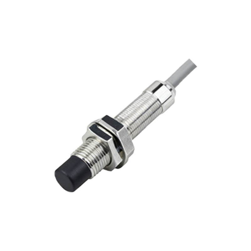
Once mechanically secured, correct electrical connection is essential. Engineers must adhere to the manufacturer's wiring diagram, connecting the power supply (commonly 10-30V DC), load, and ground correctly. Using shielded cables in electrically noisy environments is a recommended practice. After powering up, the first debug action is to verify the output signal. Most sensors feature an LED indicator that illuminates when the target is detected. A multimeter or oscilloscope can be used to monitor the output voltage or current signal. This step confirms basic functionality and helps identify wiring faults or power supply issues before proceeding to sensitivity adjustments.
Fine-Tuning Sensitivity for Optimal Performance
The heart of sensor debugging lies in sensitivity adjustment. The goal is to achieve a consistent and reliable switching point without false positives from non-target objects or environmental noise. The procedure involves presenting the standard target at the desired operating distance. Using a non-metallic adjustment tool, the sensitivity potentiometer is turned slowly until the output state changes (LED turns on/off). It is advisable to set the point slightly inside the maximum range to create a safety margin. For challenging applications with small targets or different materials, incremental adjustments while monitoring the output are necessary. Documenting the final potentiometer position is good practice for future maintenance.
Addressing Environmental Interference
Industrial environments present numerous challenges that require compensatory adjustments. Electrical noise from motors or variable frequency drives can cause erratic sensor behavior. Solutions include proper grounding, using filters, or increasing the sensor's switching hysteresis if adjustable. For capacitive sensors, changes in humidity or contamination on the sensing face can alter performance, necessitating re-calibration. In applications with multiple sensors in close proximity, mutual interference can occur. Adjusting the installation distance, orienting sensors differently, or selecting models with anti-interference features are effective debugging strategies. Temperature extremes may also affect sensing range, requiring consultation of the sensor's derating curves.
Integration with Control Systems and Diagnostics
Final debugging involves integrating the sensor into the broader machine control system, typically a PLC. The sensor's discrete signal must be correctly mapped to a PLC input module. Engineers should verify the signal's stability and timing within the control logic. Many modern sensors offer diagnostic capabilities via IO-Link or other digital protocols, providing detailed status information like operating hours, temperature, or signal strength. Utilizing these features allows for predictive maintenance and remote adjustment. Functional safety sensors (e.g., Type 3 or Type 4) require specialized, validated debugging procedures in accordance with safety standards like ISO 13849.
Maintenance and Periodic Re-calibration
A