Introduction to Slot-Type Photoelectric Sensors
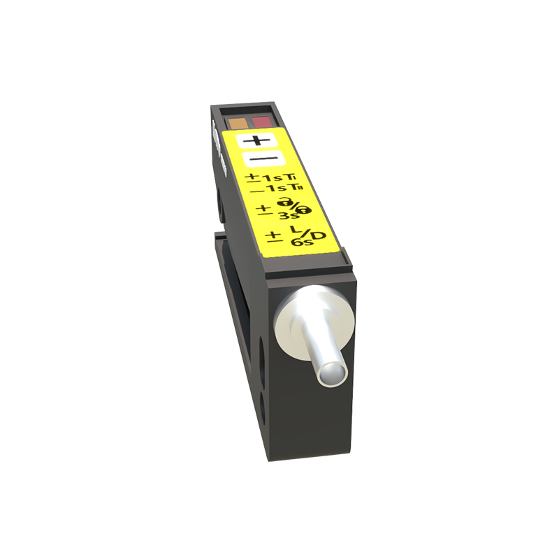
Slot-type photoelectric sensors, often called fork or through-beam sensors, are fundamental components in industrial automation for precise object detection and counting. These sensors consist of a U-shaped housing with an infrared LED emitter on one side and a phototransistor receiver directly opposite. When an object passes through the slot, it interrupts the light beam, generating a clean digital signal. This inherent physical alignment makes them highly reliable and immune to many ambient light issues compared to reflective sensors. Their primary application in counting involves monitoring items on conveyor belts, parts in assembly machines, or products during packaging. The consistent and fast response of the optical beam provides an ideal trigger for a counting system's input.
Core Principles of Counting with Digital Signals
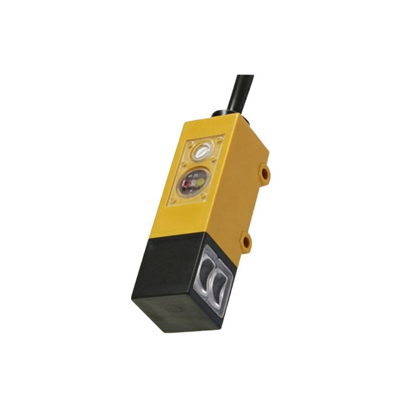
The counting logic is built upon the sensor's digital output. Typically, the sensor outputs a HIGH signal (e.g., 5V or 24V) when the beam is unbroken and a LOW signal (0V) when interrupted. A complete count event is registered on a specific edge transition of this signal. The most common method is to count on the rising edge, which occurs when the object leaves the beam and the signal returns from LOW to HIGH. This approach helps avoid double-counting caused by object vibration or irregular shapes. The system must include a debouncing routine, either in hardware or software, to filter out mechanical chatter or electrical noise that might cause multiple false triggers from a single object. Understanding this signal behavior is crucial for writing robust code.
Basic Counting Code Structure for Microcontrollers
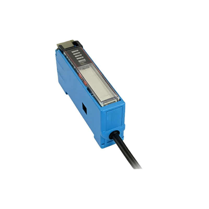
Here is a foundational code example for an Arduino-like microcontroller, demonstrating the core logic. This sketch assumes the sensor output is connected to digital pin 2, which is configured to use an internal pull-up resistor. The code counts on the rising edge, ensuring one count per object passage.
``cpp
const int sensorPin = 2; // Sensor connected to digital pin 2
volatile unsigned long count = 0; // Volatile as it's changed in an interrupt
int lastSensorState = HIGH; // Assuming pull-up, so default is HIGH
unsigned long lastDebounceTime = 0;
const unsigned long debounceDelay = 10; // milliseconds
void setup() {
Serial.begin(9600);
pinMode(sensorPin, INPUT_PULLUP);
attachInterrupt(digitalPinToInterrupt(sensorPin), countObject, CHANGE);
}
void loop() {
// Non-blocking serial print for monitoring
static unsigned long lastPrint = 0;
if (millis() - lastPrint > 1000) {
Serial.print("Total Count: ");
Serial.println(count);
lastPrint = millis();
}
// Main loop can handle other tasks
}
void countObject() {
int currentState = digitalRead(sensorPin);
// Simple software debounce check
if (currentState != lastSensorState) {
lastDebounceTime = millis();
}
if ((millis() - lastDebounceTime) > debounceDelay) {
// If the state is stable and it's a RISING edge, increment count
if (currentState == HIGH && lastSensorState == LOW) {
count++;
}
}
lastSensorState = currentState;
}
`
This structure uses an interrupt service routine (ISR) for immediate response, coupled with a debounce check for signal stability.
Advanced Implementation: Throughput Calculation and Error Handling
For industrial systems, simply counting is often insufficient. Advanced code calculates real-time throughput (parts per minute) and incorporates error handling. This involves tracking timestamps between counts. The system can detect jams (no counts for an expected period) or over-speed conditions (counts too frequent). Below is a conceptual extension of the loop function to calculate rate and check for errors.
`cpp
void loop() {
static unsigned long lastCountTime = 0;
static unsigned long lastCalcTime = 0;
float partsPerMinute = 0.0;
unsigned long currentTime = millis();
// Calculate throughput every second
if (currentTime - lastCalcTime >= 1000) {
if (lastCountTime != 0) {
// Very basic rate calc: counts in the last second * 60
// A more robust method would use a rolling buffer of timestamps
partsPerMinute = (count - lastCount) * 60;
lastCount = count;
}
lastCalcTime = currentTime;
// Error Checks
if (partsPerMinute == 0 && currentTime - lastCountTime > 5000) {
Serial.println("ALERT: Possible Jam - No parts detected in 5 seconds.");
}
if (partsPerMinute > MAX_DESIGN_RATE) {
Serial.println("ALERT: Throughput exceeding design maximum.");
}
Serial.print("PPM: ");
Serial.println(partsPerMinute);
}
// ... other tasks
}
``
This layer adds significant operational intelligence to the basic counting function.
Integration with PLC Systems (Ladder Logic Example)
In larger industrial settings, Programmable Logic Controllers (PLCs) are standard. The counting logic is often implemented in ladder logic. A typical network uses a positive transition contact (or a one-shot) triggered by the sensor's input to increment a counter register. PLCs handle debouncing and noise internally with hardware filtering on input cards. A simple ladder logic rung would use the sensor input (e.g., I:0/0) to trigger a count-up (CTU) instruction for a counter (e.g., C5:0). The counter's accumulated value (.ACC) is then used for HMIs or data logging. The robustness of PLCs lies in their deterministic scan cycle and industrial-grade noise immunity.
Best Practices for System Reliability
To ensure long-term reliability, follow these key practices. First, provide stable, clean power to the sensor, often using a separate regulated supply to avoid noise from motor drives. Second, implement proper shielding and grounding for the signal cable, especially in electrically noisy environments. Third, calibrate the sensor's sensitivity correctly for the object's size and opacity; many slot sensors have a potentiometer for this adjustment. Fourth, in code, always use unsigned long variables for counts to prevent overflow in long-running systems. Finally, include a manual reset function for the counter, accessible via a physical button or through a supervisory interface, to allow operators to reset at the start of a new batch.
Conclusion and Further Applications
Mastering the code for slot-type photoelectric sensor counting opens doors to numerous automation tasks. The fundamental principles of edge detection, debouncing, and interrupt handling are transferable. Beyond simple counting, this setup can be the trigger for subsequent actions like sorting, rejection, or initiating a machine cycle. By adding timestamps and network connectivity, the data can feed into Manufacturing Execution Systems (MES) for production tracking and analysis. Starting