Core Components and Working Principle
An inductive proximity sensor is a non-contact electronic device designed to detect the presence of metallic objects. Its fundamental operation relies on the principle of electromagnetic induction. The core component is a coil wound around a ferrite core, which forms part of an oscillator circuit. When energized, this coil generates a high-frequency alternating electromagnetic field at the active face of the sensor. In the absence of a target, the oscillator operates at a stable amplitude. When a conductive metal object enters this oscillating field, eddy currents are induced on the surface of the target. These eddy currents draw energy from the oscillator, causing a reduction in its amplitude. This amplitude change is detected by a threshold circuit, which subsequently triggers a solid-state output switch, signaling the presence of the object.
Internal Circuitry and Signal Processing
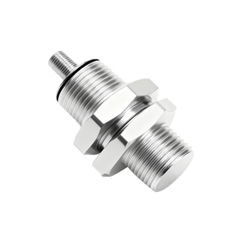
The internal construction is meticulously engineered for reliability. The oscillator circuit, typically a Colpitts or Hartley oscillator, generates the high-frequency field. Following the oscillator is a demodulator stage that converts the amplitude change into a DC voltage signal. This signal is then fed into a Schmitt trigger or a comparator circuit. The comparator evaluates the signal against a predefined threshold level, ensuring immunity to minor fluctuations and providing a clean, decisive switching action. The final stage is the output driver, which can be an NPN, PNP transistor, or a complementary pair for a push-pull configuration, providing the interface to programmable logic controllers (PLCs) or other control systems. Modern sensors often incorporate Application-Specific Integrated Circuits (ASICs) that integrate all these functions into a single chip, enhancing performance and reducing physical size.
Physical Housing and Material Selection
The housing is critical for mechanical robustness and environmental protection. Common housing materials include nickel-plated brass, stainless steel (V2A, V4A), and engineering plastics like PBT or PPS. The choice depends on the application environment—stainless steel for corrosive or washdown areas, and plastics for non-metallic sensing environments to prevent mutual interference. The active sensing face is protected by a front cap, often made of a specialized polymer (e.g., PTFE) or ceramic that allows the electromagnetic field to pass through while shielding the coil from physical damage, chips, or coolants. The housing is designed to meet specific Ingress Protection (IP) ratings, such as IP67 or IP69K, ensuring resistance to dust and high-pressure water jets.
Coil Design and Sensing Characteristics
The coil is the heart of the sensor. It is precision-wound with copper wire around a ferrite core, which concentrates the electromagnetic field. The coil's geometry—its diameter, number of turns, and winding pattern—directly determines the sensor's nominal sensing distance (Sn). Factors like the target material, size, and shape also influence the effective sensing range. For instance, steel is detected at the rated distance, while stainless steel or aluminum may reduce the range due to lower permeability and higher resistivity. Advanced sensors feature compensated coils or shielding to create a more focused field pattern, minimizing side and rear sensing effects and allowing for flush mounting in metal surrounds.
Output Configuration and Wiring
Inductive sensors offer various output types to interface with control systems. The two primary DC configurations are NPN (sinking) and PNP (sourcing), defined by the type of output transistor. Wiring is typically via a pre-attached cable or a quick-disconnect (QD) connector, commonly following the M8, M12, or M23 standard. A standard 3-wire design includes connections for supply voltage (V+), ground (0V), and the switched output signal. Many sensors also feature a diagnostic LED indicator. Some models offer analog (4-20mA, 0-10V) or IO-Link digital outputs, providing continuous distance information rather than a simple on/off switch, enabling more advanced process monitoring.
Shielded vs. Unshielded Designs
A key design distinction lies in shielding. Shielded (flush-mountable) sensors have a metallic ring surrounding the coil, which confines the electromagnetic field primarily to the front. This allows them to be installed flush in a metal mounting bracket without the bracket being detected, saving space. Unshielded (non-flush mountable) sensors have a more extended field and offer a longer sensing range for the same housing size but require a non-metallic surround to operate correctly. The choice between shielded and unshielded is a fundamental application decision impacting mounting, sensing distance, and installation density.
Environmental Considerations and Protection
Industrial environments pose challenges like temperature extremes, voltage spikes, and electromagnetic interference (EMI). Internally, components