Understanding Proximity Sensor Fundamentals
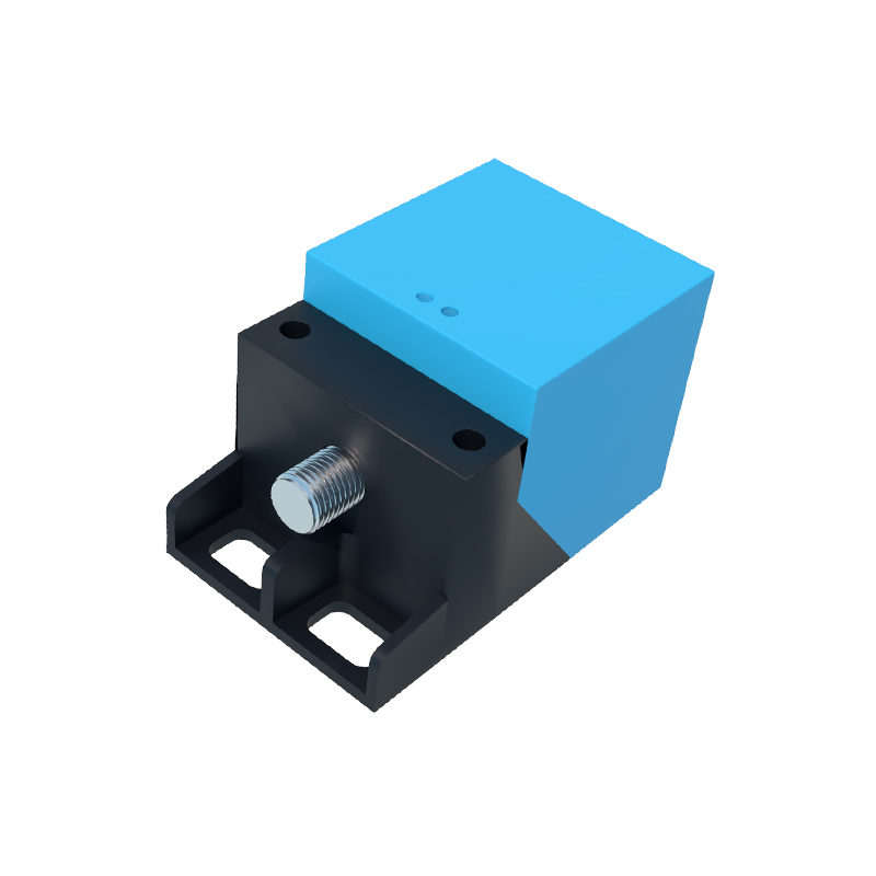
Proximity sensors are indispensable components in modern conveyor systems, providing non-contact detection of metallic or non-metallic objects. Before wiring, it is crucial to understand the sensor type you are handling. Inductive sensors detect metallic objects, while capacitive sensors can detect a wider range of materials, including liquids and plastics. The two primary electrical configurations are PNP (sourcing) and NPN (sinking). PNP sensors switch the positive voltage to the load, whereas NNP sensors switch the negative or ground side. Most conveyor applications in North America and Europe standardize on PNP sensors for their compatibility with PLC (Programmable Logic Controller) input modules. Always consult the sensor's datasheet to confirm its type, voltage rating (commonly 10-30V DC), output configuration, and sensing range. Incorrect identification is a leading cause of installation failure and potential damage.
Essential Tools and Safety Precautions
Gather all necessary tools and materials before starting. You will typically need a screwdriver set, wire strippers, crimping tools, appropriate gauge wires (often shielded cable for noise immunity), ferrules, and a multimeter. The paramount rule is to lock out and tag out (LOTO) the conveyor's power supply. Verify zero energy state using a multimeter. Wear appropriate personal protective equipment (PPE). Ensure the work area is clean and dry. Plan the cable routing away from high-voltage power lines and motor drives to minimize electromagnetic interference, which can cause erratic sensor behavior. Using conduit or cable trays is recommended for organized and protected installation.
Step-by-Step Wiring Procedure for a Standard 3-Wire DC Sensor
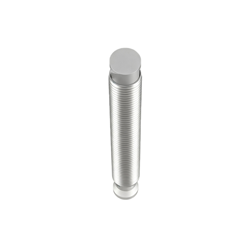
A standard 3-wire DC proximity sensor has brown, blue, and black wires. The brown wire is for the positive supply voltage (+V), and the blue wire is for the common negative or ground (0V). The black wire is the signal output line. First, run the sensor cable from the sensor location to the control cabinet. Connect the blue wire to the DC power supply's negative terminal or the common ground point in the cabinet. Next, connect the brown wire to the positive terminal of the power supply, ensuring the voltage matches the sensor's specification. Finally, connect the black output wire to the designated input channel on your PLC, relay, or controller. For a PNP sensor, this input point will internally connect to ground, completing the circuit when the sensor activates.
Integrating with the Control System
The sensor's output must be correctly integrated into the conveyor's control logic. When the sensor detects an object, its output state changes—typically from 'off' to 'on' for a normally open (NO) configuration. This signal is read by the PLC input module. In the PLC program, this input is used to trigger actions such as stopping a conveyor zone, initiating a pusher, incrementing a counter, or starting a timing sequence. It is good practice to use an intermediate relay for high-current loads, even if the sensor is rated for it, to protect the sensor contacts. Always include diagnostic indicators; many sensors have built-in LEDs, but adding a pilot light on the control panel for critical sensors aids in troubleshooting.
Testing and Commissioning the Installation
After wiring, do not immediately restore full power. First, perform a continuity and short-circuit check with a multimeter. Then, energize the control circuit. Observe the sensor's indicator LED. It should be on steadily when no target is present (for a NO sensor) or blink according to its manual. Introduce a target object (e.g., a metal bracket for an inductive sensor) within its sensing range. The LED should change state, and the corresponding input LED on the PLC should illuminate. Use the PLC's software to monitor the real-time status of the input. Test the sensor at various points along its sensing face to verify consistent detection. Finally, conduct a full system test with the conveyor running at low speed to ensure the sensor triggers the programmed control actions correctly and reliably.
Common Troubleshooting and Best Practices
If the sensor fails to operate, follow a systematic approach. Check power: verify voltage between brown and blue wires. Check wiring: ensure connections are tight and correct. Check the target: is it the correct material and size? Is it within the sensing range? Check for interference: reroute cables away from noise sources. Ensure the sensor is not overloaded by checking the load current against the sensor's rating. For long-term reliability, implement best practices: use strain relief at cable entries, secure cables properly to prevent vibration damage, label all wires clearly, and establish a regular maintenance schedule to