Introduction to Proximity Sensors
Proximity sensors are indispensable components in modern industrial automation, providing non-contact detection of metallic or, in some cases, non-metallic objects. Among the various configurations, the 3-wire sensor is the most prevalent and versatile design found in countless applications, from assembly lines and robotic systems to packaging machinery and safety interlocks. Unlike mechanical limit switches, these sensors offer high reliability, long operational life, and fast response times without physical wear and tear. Their fundamental principle relies on generating an electromagnetic field and detecting changes caused by a target object entering this field. The 3-wire design specifically provides a robust interface for power supply and signal output, making integration into standard control systems straightforward and efficient.
Core Operating Principle: Inductive Sensing
The majority of 3-wire proximity sensors operate on the inductive principle. At the heart of the sensor is an oscillator circuit that generates a high-frequency electromagnetic field at the sensing face. This field is emitted from a coil wound around a ferrite core. When a conductive metal target enters this active field, eddy currents are induced on the surface of the target. These eddy currents draw energy from the oscillator, causing a reduction in its amplitude. An evaluation circuit within the sensor continuously monitors the oscillator's amplitude. Once the amplitude drop exceeds a predefined threshold—indicating the target is within the specified sensing range—the sensor's output state changes. This entire process happens without any physical contact, allowing for detection through non-metallic barriers and in dirty or wet environments.
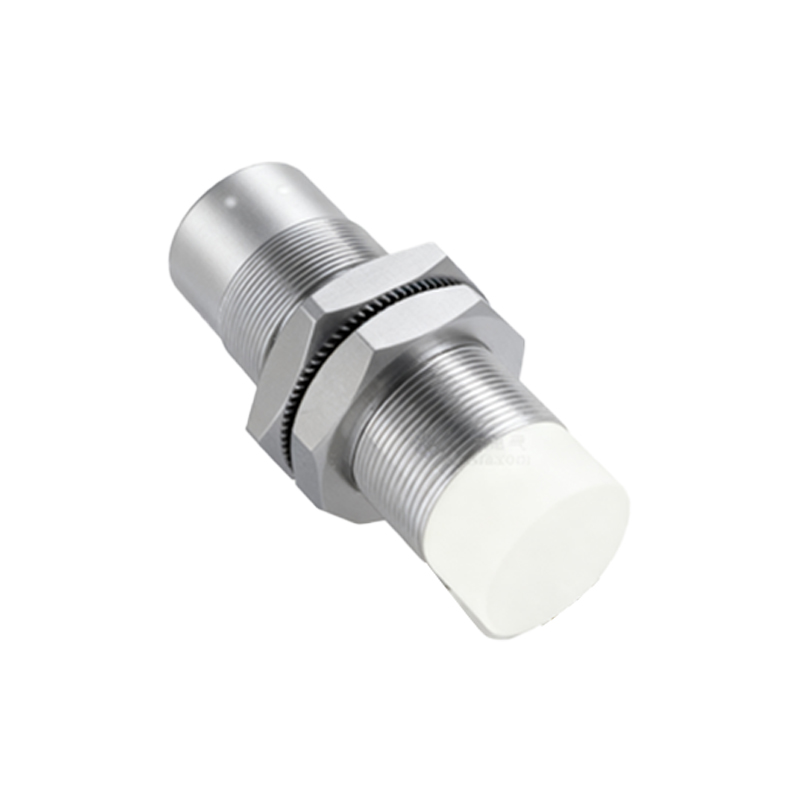
Anatomy of the Three Wires
The functionality of a 3-wire sensor is defined by its wiring. The three wires are typically color-coded as brown, blue, and black (following international standards like IEC 60947-5-2). The brown wire is connected to the positive supply voltage (e.g., +24V DC). The blue wire is connected to the common negative or 0V of the power supply. These two wires provide the necessary operating power for the sensor's internal electronics, including the oscillator, amplifier, and output switching circuit. The third wire, usually black, is the signal output line. The nature of this output—whether it is Normally Open (NO) or Normally Closed (NC)—and its type—sourcing (PNP) or sinking (NPN)—determines how the signal is presented to the controller, such as a Programmable Logic Controller (PLC).
Output Types: PNP vs. NPN Sourcing
This is a critical distinction in 3-wire sensor operation. A PNP (sourcing) sensor switches the positive voltage. In its active state (target detected), the black output wire connects internally to the positive supply (brown wire), sourcing current to the load (e.g., a PLC input). The load is connected between the black wire and the negative supply (blue). Conversely, an NPN (sinking) sensor switches the negative path. When active, the black output wire connects internally to the negative supply (blue wire), sinking current from the load. Here, the load is connected between the positive supply and the black wire. The choice between PNP and NPN depends on the control system's architecture and the prevailing convention in a region (PNP is common in Europe, NPN in some Asian markets).
The Internal Switching Element
The actual switching of the output signal is performed by a solid-state device, almost universally a transistor. This transistor acts as an electronic switch, replacing the moving contacts found in electromechanical relays. For a PNP output sensor, a PNP transistor is used. When the evaluation circuit triggers, it allows current to flow from the emitter (connected to +V) to the collector (connected to the output wire). For an NPN sensor, an NPN transistor is used, allowing current to flow from the collector (connected to the output/load) to the emitter (connected to 0V). The use of a transistor provides incredibly fast switching speeds, in the order of microseconds, and eliminates contact bounce, ensuring clean, reliable signal transitions for high-speed counting or positioning applications.
Wiring Configuration and Load Connection
Proper wiring is essential for reliable operation. For a typical PNP sensor, the brown wire goes to +24V DC, the blue wire to 0V DC, and the black wire to the input module of the controller. The controller input module itself must be configured to accept a sourcing signal; it internally connects the input point to 0V through a pull-down resistor. When the sensor detects a target, the black wire sources +24V to the PLC input,