Introduction to Photoelectric Sensors in Ice Making
Photoelectric sensors are critical components in modern automatic ice makers, primarily responsible for detecting the ice level within the storage bin. These sensors operate on the principle of light beam interruption or reflection. A typical setup involves an emitter, which projects an infrared or visible light beam, and a receiver positioned opposite or adjacent to it. When ice cubes accumulate to a predetermined height, they obstruct the light path. The receiver detects this change in light intensity, sending a signal to the control board to halt the ice production cycle. This mechanism prevents overfilling, ensures efficient operation, and is fundamental to the "ice-full" detection system. The reliability and precision of these sensors directly impact the machine's performance and energy consumption.
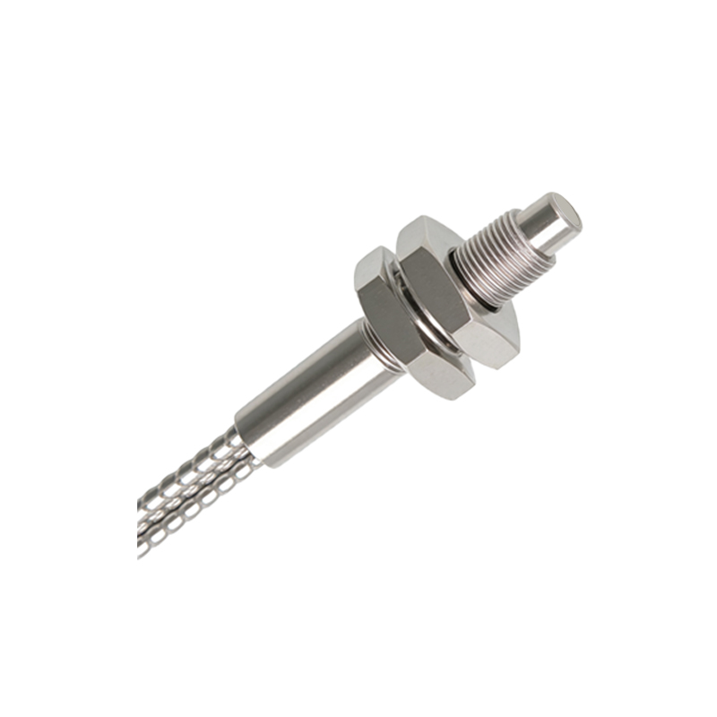
Analyzing Common Photoelectric Sensor Image Configurations
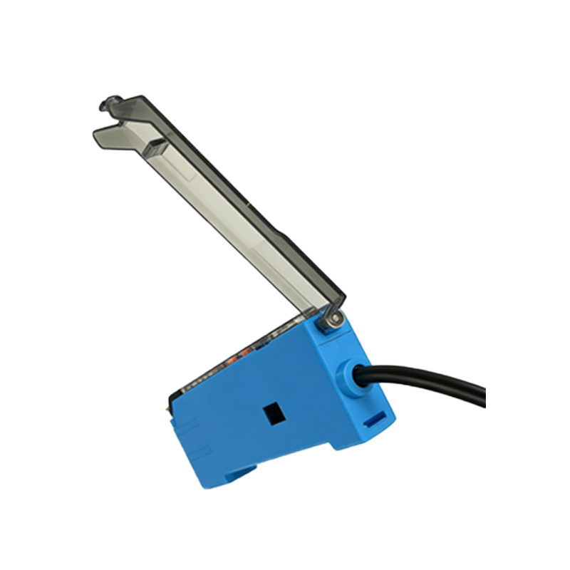
Technical documentation and service manuals often contain specific images and diagrams of these sensors. A standard direct-through beam (opposed) sensor image will show two distinct components: the emitter and the receiver, housed in separate units mounted on opposite sides of the ice bin's interior walls. The emitter lens and receiver lens are clearly aligned. In contrast, a retro-reflective sensor image depicts a single housing containing both the emitter and receiver, facing a dedicated reflector mounted on the opposite wall. The light path in the image is often illustrated with a dashed line. Diffuse (proximity) sensor images show a single unit where the emitted light reflects off the ice surface back to the receiver within the same housing. These images are crucial for identifying sensor type during troubleshooting or replacement.
Key Visual Indicators in Sensor Imagery for Diagnostics
When examining photoelectric sensor images for diagnostic purposes, engineers must focus on several visual details. First, observe the lens condition; any image showing cracks, cloudiness, or significant dust accumulation on the lens surface indicates potential failure. Second, examine the alignment marks. Many sensor housings have alignment arrows or notches. In installation diagrams, misalignment between these marks on the emitter and receiver is a common cause of fault. Third, wiring diagrams accompanying the images are vital. Look for the color-coding of wires (typically brown for +V, blue for common, black for output) and their connection points on the sensor's terminal block or connector. Corrosion or bent pins at these connections, if visible in detailed photos, points to electrical issues.
Impact of Ice and Frost Accumulation on Sensor Performance
A frequent challenge depicted in real-world service case images is the accumulation of frost or ice directly on the sensor lens or housing. This layer acts as an opaque barrier, scattering or blocking the light beam and causing false "ice-full" signals or a complete failure to detect ice. Images from field service reports often show sensors completely encased in a block of frost. This highlights the importance of the sensor's environmental sealing rating (e.g., IP67) and the design of any built-in heater elements. Some advanced sensor images include a heating coil diagram around the lens area to illustrate anti-frost functionality. Engineers must ensure that any replacement sensor matches the original's specifications for temperature range and frost resistance.
Selecting Replacement Sensors Based on Technical Images
Choosing a correct replacement sensor requires meticulous comparison of the original unit's images with candidate datasheets. Beyond physical dimensions and mounting hole patterns, engineers must match the optical characteristics. Key specifications visible or inferred from technical drawings include the sensing range (e.g., 0-5 meters), light source type (infrared LED is most common), output type (NPN/PNP transistor, normally open/closed), and supply voltage (commonly 12-24V DC). The beam pattern diagram, often shown as an angular dispersion graph, indicates the sensor's sensitivity area and must be compatible with the ice bin's geometry. Ignoring these details, visible in cross-sectional or performance characteristic images, can lead to unreliable detection and repeated service calls.
Future Trends: Smart Sensors and Image-Based Monitoring
The evolution of photoelectric sensors in ice makers is moving towards integrated smart sensors with diagnostic capabilities. Future system images may show sensors with integrated microprocessors and LED status indicators that communicate directly with building management systems via IO-Link or similar protocols. Furthermore, the use of machine vision is emerging. Instead of a single-point beam, a small camera module (images of which resemble a compact lens array) captures images of the ice pile. Image processing algorithms then analyze the pile's volume and shape. These systems provide more granular data beyond a simple full/empty binary signal, enabling predictive maintenance and optimized harvest cycles, representing the next frontier in ice maker control technology.