Understanding the Roller Photoelectric Sensor
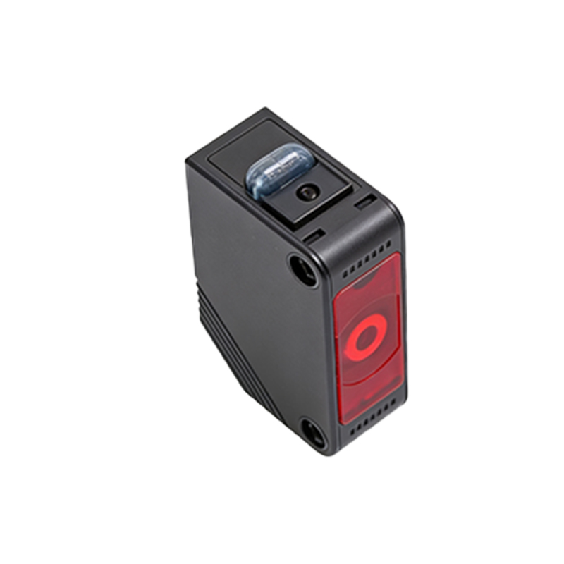
Roller photoelectric sensors are critical components in industrial automation, commonly used for detecting object presence, counting, and positioning on conveyor systems. These sensors combine a mechanical roller arm with an optical sensing mechanism. When an object contacts the roller, it triggers an internal mechanism that interrupts or reflects a light beam, generating an electrical signal. This design allows for precise detection without direct contact with the object surface, reducing wear and tear. Typical applications include packaging lines, material handling systems, and assembly stations. Before replacement, it is essential to understand the sensor's specifications, such as voltage rating (e.g., 10-30V DC), output type (PNP/NPN), and response time, to ensure compatibility with the existing system.
Safety Precautions and Preparation
Prior to any maintenance work, adhering to safety protocols is paramount to prevent accidents and equipment damage. Begin by de-energizing the electrical circuit powering the sensor and the associated machinery. Lock out and tag out (LOTO) the power source to avoid accidental re-energization. Wear appropriate personal protective equipment (PPE), including insulated gloves and safety glasses. Gather necessary tools: screwdrivers, wrenches, a multimeter for testing, and the replacement sensor. Document the existing wiring configuration by taking photos or sketching diagrams, noting wire colors and terminal assignments. This step minimizes errors during reinstallation and ensures system integrity post-replacement.
Removing the Faulty Sensor
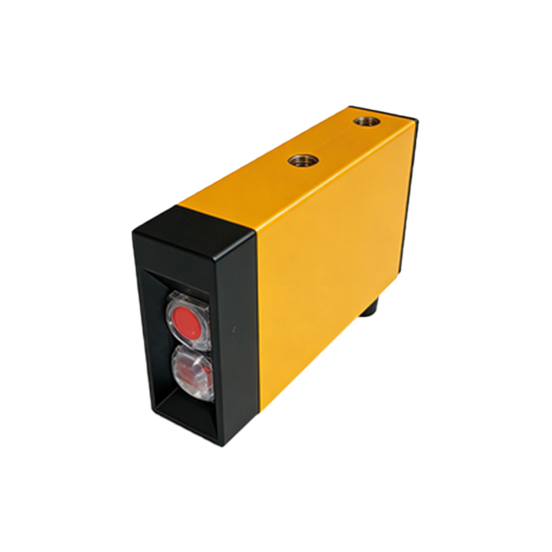
Start by disconnecting the sensor from the mounting bracket. Loosen the fastening screws or bolts that secure the sensor housing to the bracket or machine frame. Carefully detach the electrical connector from the sensor body. If the connector is secured with locking tabs, release them gently to avoid breakage. Use the multimeter to verify that no voltage is present in the wires. Once disconnected, remove the sensor completely from its position. Inspect the mounting area for any signs of damage, corrosion, or misalignment that might have contributed to sensor failure. Clean the area if necessary to ensure a stable base for the new sensor.
Installing the New Roller Photoelectric Sensor
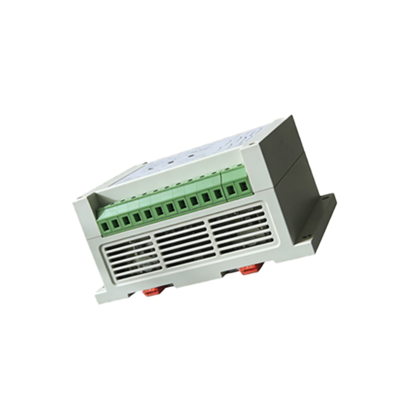
Unpack the replacement sensor and compare its specifications with the old unit to confirm they match. Position the new sensor onto the mounting bracket, aligning it precisely as per the original orientation. Secure it using the provided screws or bolts, ensuring it is firmly attached without over-tightening, which could distort the housing. Reconnect the electrical connector to the sensor, following the previously documented wiring diagram. Double-check that each wire is inserted into the correct terminal—typically, brown for positive, blue for negative, and black for output. Ensure the connector is fully seated and locked to prevent loose connections that could cause intermittent faults.
Alignment and Calibration Procedures
Proper alignment is crucial for reliable sensor operation. Adjust the roller arm so it moves freely and returns to its neutral position without obstruction. For through-beam sensors, align the emitter and receiver units so the light beam is unobstructed and centered. Use alignment tools if provided by the manufacturer. Power on the system temporarily to test the sensor's response. Observe the indicator LED—usually green for power and yellow for detection—to confirm correct operation. If the sensor features sensitivity adjustments, calibrate it by passing a test object through the detection zone and fine-tuning the potentiometer until consistent signals are achieved. Avoid over-sensitive settings that may trigger false detections.
Testing and Verification
After installation and calibration, conduct comprehensive testing to validate performance. Simulate normal operating conditions by running the conveyor or machinery at various speeds. Use test objects of different sizes and materials to ensure the sensor detects reliably across the expected range. Monitor the output with a multimeter or oscilloscope to verify signal stability and timing. Check for any abnormal noises or resistance in the roller movement, which could indicate mechanical issues. Document the test results, including response times and any adjustments made. Finally, integrate the sensor into the control system and run a full operational cycle to ensure seamless interaction with other components like PLCs or motor drives.
Maintenance Tips for Longevity
To extend the lifespan of the new roller photoelectric sensor, implement regular maintenance routines. Periodically inspect the roller mechanism for debris buildup, lubricating moving parts as recommended by the manufacturer. Clean the optical lenses with a soft, lint-free cloth to maintain light transmission efficiency. Avoid exposing the sensor to excessive vibration, moisture, or temperature extremes beyond its rated specifications. Schedule routine electrical checks to monitor voltage stability and connection integrity. Keep a log of maintenance activities and performance metrics to identify trends or early signs of wear, enabling proactive replacements before failures disrupt production.