Understanding the GTB6 Photoelectric Sensor
The GTB6 series represents a versatile line of photoelectric sensors widely used in industrial automation for detection, positioning, and counting applications. These sensors operate by emitting a light beam—typically infrared, red, or laser—and detecting changes in the received light intensity caused by the presence or absence of a target object. Key variants include through-beam, retro-reflective, and diffuse reflective models, each with distinct operating principles and installation requirements. Before initiating any debug procedure, it is crucial to verify the specific model type, its sensing range, light source, and output configuration (e.g., NPN/PNP, analog, or digital). Familiarity with the sensor's datasheet, including its electrical characteristics, response time, and environmental ratings (IP67 protection is common), forms the foundation for effective troubleshooting. Ensure the sensor is correctly powered within its specified voltage range, typically 10-30V DC, and that wiring connections to the power supply and load (such as a PLC input or relay) are secure and conform to the terminal diagram.
Initial Power and Connection Checks
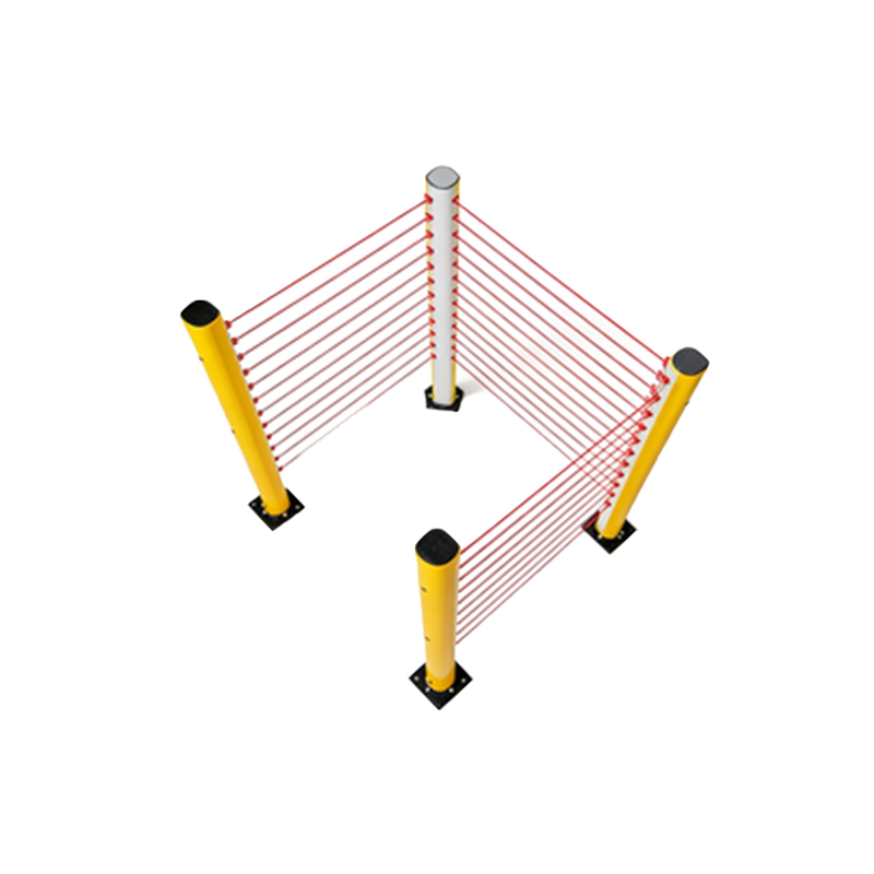
Begin the debug process with a thorough inspection of the electrical and physical setup. Power on the sensor and observe its indicator LEDs. A stable power LED (often green) confirms correct voltage supply. The output or signal LED (usually yellow or orange) indicates the sensor's detection state. If the power LED is off, immediately check the polarity of the power connections, fuse integrity, and voltage level at the sensor terminals using a multimeter. For sensors with teach-in or program functions, ensure no accidental mode activation has occurred. Verify that the load is correctly connected and its impedance matches the sensor's output specifications. Loose wires, corrosion, or short circuits in the cable or connector can cause intermittent failures. Physically inspect the sensor housing and lens for dirt, dust, condensation, or mechanical damage that could obstruct the light path. Even minor contamination can significantly reduce sensing reliability, especially in diffuse reflective modes.
Aligning the Optical Path
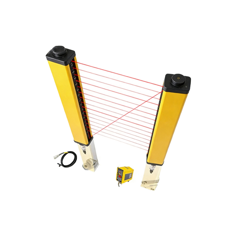
Proper alignment is critical for through-beam and retro-reflective sensors. For a through-beam type, carefully align the separate emitter and receiver units so that the light beam is perpendicular to the target path and centered on the receiver's lens. Use the sensor's alignment indicators if available. A misaligned beam may still provide a weak signal, leading to unstable operation. For retro-reflective models, ensure the reflector is clean, correctly oriented, and within the specified sensing distance. Avoid angular misalignment between the sensor and reflector. Diffuse sensors require precise positioning relative to the target's surface, color, and material, as they rely on reflected light. In all cases, minimize background reflections from shiny surfaces and avoid cross-talk from other light sources or adjacent sensors. Temporarily increasing the sensor's sensitivity during alignment can help find the optimal position before setting it to the final operational value.
Configuring Sensitivity and Response Time
Most GTB6 sensors feature a sensitivity potentiometer or digital settings to adjust the detection threshold. If the sensor triggers falsely or fails to detect, adjust the sensitivity. Turn the potentiometer clockwise to increase sensitivity (for detecting smaller or less reflective objects) or counterclockwise to decrease it (to ignore background objects or reduce noise). Make small adjustments while testing with the actual target. Additionally, configure the response time or switching frequency to match the application speed. A setting that is too fast may cause chatter from vibration or electrical noise, while too slow a response might miss rapid object movements. Some models offer functions like one-touch teaching or background suppression, which can simplify setup for complex surfaces. Always refer to the manual for specific adjustment procedures, as incorrect settings can lead to unreliable operation.
Diagnosing Output and Signal Issues
When the sensor indicates detection via its LED but the control system does not register a signal, diagnose the output circuit. Use a multimeter to measure the voltage at the output terminal relative to the common wire during activation. For a sinking (NPN) output, the voltage should drop near 0V when active; for a sourcing (PNP) output, it should rise close to the supply voltage. If the voltage does not change, the sensor's output transistor may be damaged. Ensure the load's current draw does not exceed the sensor's maximum switching capacity. For analog output versions, verify the output current or voltage corresponds linearly to the measured distance or intensity. Noise interference from motors, drives, or power lines can disrupt signals; use shielded cables, separate wiring paths, and proper grounding to mitigate this. In networked or smart sensor setups, check communication protocols and address settings.
Testing Environmental and Application Factors
Environmental conditions profoundly affect photoelectric sensor performance. High ambient light, especially from direct sunlight or strobes, can saturate the receiver. Install protective shrouds or use sensors with modulated light (typically a pulsed LED) that ignores constant ambient light. Temperature extremes may cause condensation or shift electronic parameters; select models with appropriate temperature ratings. Vibration can loosen mounts or connections—ensure robust mechanical fixation. For detecting transparent, glossy, or variably colored objects, you may need to adjust the sensor angle, use a polarized filter (available on some GTB6 models), or switch to a different sensing mode. Always test with the actual target material under real operating conditions, as laboratory bench tests may not reveal application-specific issues like varying object sizes or conveyor speeds.
Implementing Advanced Troubleshooting Steps
If basic checks and adjustments fail, proceed with systematic troubleshooting. Substitute the sensor with a known-working unit of the same model to isolate whether the problem lies with the sensor or the external system. Use an oscilloscope to examine the emitter's light pulse and the receiver's signal if accessible, checking for proper amplitude and waveform. Monitor the power supply line for voltage dips or electrical noise spikes during operation. Consult the sensor's error indication patterns—some models flash specific LED sequences to denote conditions like overload, short circuit, or alignment error. Review the application design: perhaps the sensing distance is too marginal, the target is too small, or the required switching frequency exceeds the sensor's capability. In such cases, reconsider the sensor type or installation location. Document all findings and parameter settings for future reference and maintenance.
Final Verification and Best Practices
After debugging, conduct a prolonged run-in test under normal operating conditions to ensure stability. Confirm consistent detection over hundreds or thousands of cycles. Seal any unused adjustment potentiometers with locking glue or covers to prevent accidental drift. Establish a preventive maintenance schedule that includes regular lens cleaning, alignment verification, and connection checks. Keep the sensor's operating manual and datasheet readily accessible. Remember that successful debugging of GTB6 photoelectric sensors combines methodical electrical checks, precise optical alignment, appropriate parameter configuration, and a thorough understanding of the specific application environment. This disciplined approach minimizes downtime and ensures reliable, long-term sensor performance in demanding industrial automation systems.
SEO