Understanding Proximity Sensor Fundamentals
Proximity sensors are indispensable components in modern industrial automation, detecting the presence or absence of an object without physical contact. These sensors operate on various principles, including inductive, capacitive, and photoelectric technologies. Inductive sensors, for instance, generate an electromagnetic field to detect metallic targets, while capacitive sensors can sense both metallic and non-metallic materials by measuring changes in capacitance. Before delving into wiring diagrams, it is crucial to select the correct sensor type (NPN or PNP, normally open or normally closed) based on the control system's requirements. A solid grasp of these fundamentals ensures a correct interpretation of any wiring schematic and prevents common installation errors that could lead to system malfunctions.
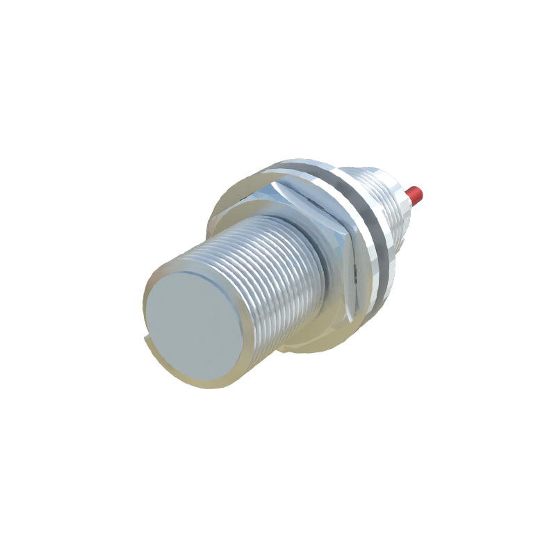
Essential Components and Tools for the Experiment
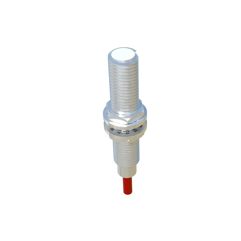
To conduct a successful proximity sensor wiring experiment, a specific set of components and tools is required. The primary items include the proximity sensor itself (e.g., a 12-24V DC inductive sensor), a compatible DC power supply, a programmable logic controller (PLC) or a relay module for interfacing, indicator LEDs or a multimeter for signal verification, and the target object (typically a piece of metal). Necessary tools comprise a set of screwdrivers, wire strippers, electrical tape, and a breadboard or terminal blocks for secure connections. Always prioritize safety by ensuring the power supply is disconnected during the initial wiring phase and by using appropriately rated components to prevent electrical hazards.
Detailed Wiring Diagram and Step-by-Step Connection
This section outlines a standard wiring configuration for a three-wire DC proximity sensor (Brown, Blue, Black wires) connected to a PLC digital input. First, connect the Brown wire (typically +V or positive supply) to the positive terminal of your DC power supply (e.g., +24V). Connect the Blue wire (0V or negative/common) to the negative terminal of the same power supply. The Black wire is the signal output line. For an NPN sensor (sinking output), connect the Black wire to the PLC's digital input terminal. Then, connect the same PLC input terminal, via an internal or external circuit, to the positive supply (+24V) to complete the circuit. For a PNP sensor (sourcing output), the Black wire provides the positive signal, so the PLC input must be connected to the common negative. Always cross-reference the sensor's datasheet, as wire colors can vary by manufacturer.
Powering Up and Initial Functional Testing
After double-checking all connections against the wiring diagram, apply power to the system. Begin by energizing only the sensor's power circuit (Brown and Blue wires). A built-in LED on the sensor housing should illuminate, indicating it has power. Next, introduce the target metal object within the sensor's specified sensing range. Observe the sensor's signal LED; it should activate when the target is detected. Using a multimeter set to DC voltage, measure the voltage between the Black signal wire and the Blue common wire. With no target present, an NPN sensor should show a high voltage (near supply voltage), which drops to a low voltage (near 0V) when a target is detected. This verifies the sensor's switching function is operational before integrating it with the control logic.
Integrating with a PLC and Programming Basic Logic
With the sensor physically wired and functionally tested, integration with the control system is the next step. Ensure the PLC is powered correctly and its input module is configured to match the sensor type (sinking for NPN, sourcing for PNP). In the PLC programming software (e.g., TIA Portal, RSLogix, or similar), create a simple ladder logic rung. Use the address of the digital input to which the sensor is connected as a normally open (NO) or normally closed (NC) contact, depending on the desired logic. For example, a rung with the sensor's input contact can energize a coil controlling an output, such as a pilot light or a relay. Download and run the program on the PLC. The programmed output should now respond precisely to the presence or absence of the target, confirming successful integration.
Troubleshooting Common Wiring and Signal Issues
Even with careful setup, issues may arise. A frequent problem is no sensor response. First, verify power supply voltage at the sensor terminals. If absent, check fuse, wiring, and connections. If power is present but the signal doesn't change, ensure the target material and size are within specifications (for inductive sensors). Incorrect wiring between NPN/PNP sensors and the PLC input is a common culprit; review the diagram. Signal instability or erratic behavior can be caused by electrical noise. Implement mitigation strategies such as