Fundamental Operating Principles
Photoelectric sensors function by emitting a light beam, typically from an LED or laser diode, and detecting changes in the received light intensity. The core principle involves the interaction between this emitted light and the target object. In automated systems, these sensors provide non-contact detection crucial for positioning, counting, and inspection. The choice between Light Operate and Dark Operate modes fundamentally alters the sensor's response logic to the presence or absence of light, forming the basis for reliable operation in diverse industrial environments. Selecting the correct mode is paramount for ensuring system stability and preventing erroneous machine cycles.
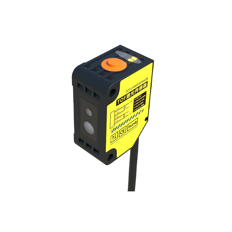
Defining Light Operate Mode (LO)
Light Operate mode, often termed "Light-On" operation, configures the sensor's output to switch to its active state when the receiver detects the emitted light beam. This mode is typically used in through-beam and retro-reflective sensor configurations. When the light path is uninterrupted and the receiver obtains sufficient light intensity, the sensor's output transistor turns on, signaling a "true" or "detected" condition. A common application is detecting the presence of a transparent object on a conveyor; the sensor output remains active while light passes through, only switching off if the object becomes opaque or moves out of alignment. This mode provides a straightforward "light present = output on" logic that is intuitive for many presence-detection tasks.
Defining Dark Operate Mode (DO)
Conversely, Dark Operate mode, or "Dark-On" operation, activates the sensor's output when the received light intensity falls below a predetermined threshold. In this mode, the output switches on when the light beam is blocked or sufficiently attenuated. This is the standard mode for diffuse reflective sensors, where the output activates when a target object reflects the beam back to the receiver. However, through-beam sensors can also use this mode. For example, in a safety curtain application, the output is normally on when the beam is received; if an object breaks the beam, the output switches off to trigger a machine stop. The logic is "light absent = output on," which is often safer for critical fault detection.
Key Differences and Electrical Output Behavior
The primary distinction lies in the output signal's relationship to the light state. An LO sensor has an active output with light reception, while a DO sensor has an active output when light is blocked. This is often implemented via a selector switch or software configuration on the sensor body. Electrically, for a standard NPN sinking output, the LO mode means the output terminal connects to ground (allowing current to sink) when light is received. In DO mode, the output terminal connects to ground when light is blocked. For PNP sourcing outputs, the logic is inverted accordingly. Understanding this electrical behavior is critical for correctly wiring the sensor into a programmable logic controller (PLC) input module to ensure the logic in the control program matches the physical state.
Application-Specific Selection Criteria
Choosing between LO and DO modes depends heavily on safety, fail-safe requirements, and logical clarity within the machine control sequence. A fundamental rule is to design for a fail-safe condition. If a sensor failure (like a burnt-out emitter, broken cable, or severe lens contamination) should cause a machine to stop for safety, the system should default to a "dark" condition. Therefore, for critical safety interlock or over-travel detection, a through-beam sensor in Dark Operate mode is often mandated. In this setup, a continuous light beam holds the output off; any break in the beam (whether by a target or a fault) activates the output to trigger a stop. For general purpose object detection where a broken beam signifies a fault, Light Operate might be more suitable to maintain operational continuity.
Integration with Control System Logic
The sensor's operating mode must align seamlessly with the ladder logic or function block programming in the controller. An LO sensor's physical "on" state (light received) should typically correspond to a "true" or "1" in the program for a normal run condition. A DO sensor's physical "on" state (light blocked) might represent a "true" for a fault condition. Programmers must account for this to avoid inverted logic. Many modern sensors offer programmable outputs or dual independent outputs, allowing one sensor to provide both LO and DO signals simultaneously for maximum flexibility. This feature simplifies control logic by providing both normal and inverted signals from a single sensing point, reducing hardware count and potential wiring errors.
Configuration and Troubleshooting Tips
Always verify the operate mode during installation and after any maintenance. Misconfigured modes are a common source of machine malfunction. Use the sensor's indicator LED as a first diagnostic step: it usually shows the state of the output transistor, not the light reception. In LO mode, the indicator is on when light is received. In DO mode, the indicator is on when light is blocked. For troubleshooting, systematically check: the actual light reception status (some sensors have a separate reception strength indicator), the selected mode, the wiring (sinking vs. sourcing relative to the PLC input), and the expected logic in the control program. Remember that ambient light interference or highly reflective backgrounds can cause unexpected switching in diffuse sensors, which may necessitate a mode change or different sensing technique.