Introduction to Photoelectric Speed Measurement
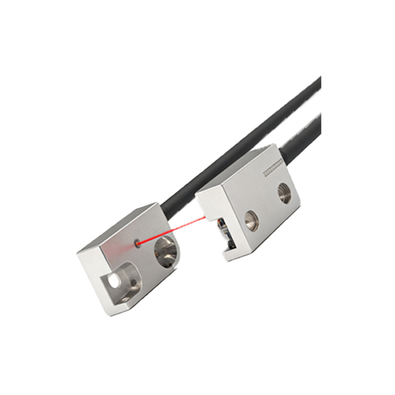
Photoelectric sensors have become a cornerstone technology for non-contact speed measurement in various industrial and research applications. This experiment focuses on analyzing the data obtained from a standard setup using a through-beam photoelectric sensor paired with a rotary encoder disc. The core principle involves the sensor detecting interruptions in a light beam caused by the slots in the rotating disc. By precisely measuring the time between successive pulses, the rotational speed of the shaft can be calculated with high accuracy. This method is favored for its reliability, fast response time, and immunity to electromagnetic interference, making it suitable for environments where traditional mechanical tachometers might fail.
Experimental Setup and Methodology
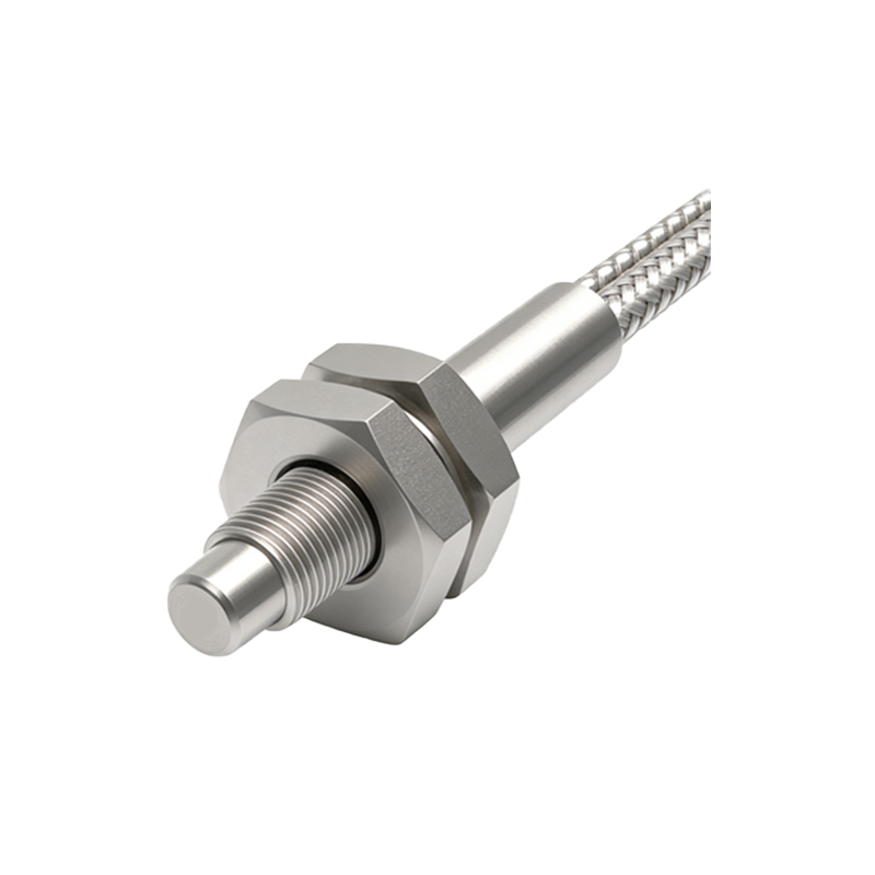
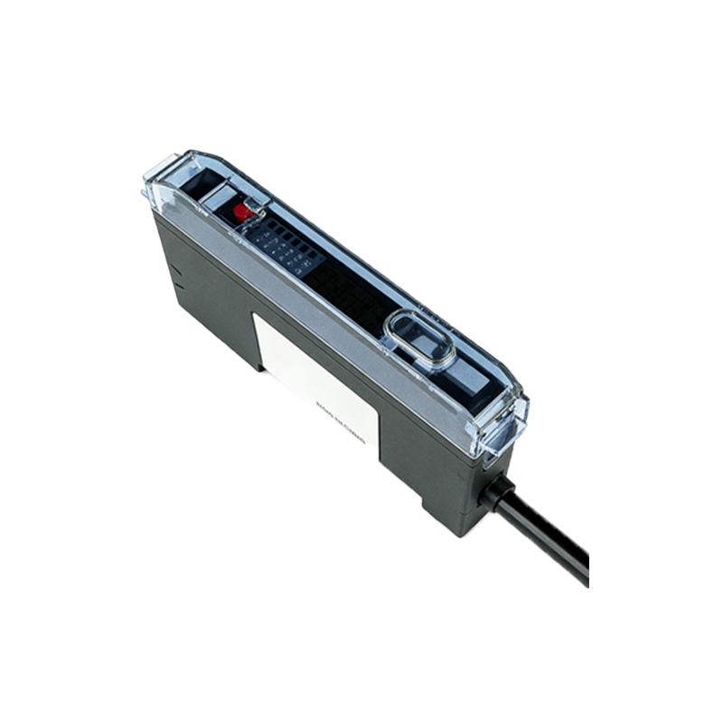
The experimental apparatus consisted of a DC motor with variable speed control, a slotted encoder disc directly mounted on the motor shaft, and a through-beam photoelectric sensor assembly. The sensor's emitter and receiver were aligned on opposite sides of the disc. The output signal from the sensor was connected to a digital frequency counter and a data acquisition (DAQ) card interfaced with a computer. The motor speed was adjusted in increments from 100 RPM to 3000 RPM using a calibrated controller. At each set speed, data was collected over a 30-second interval to capture the pulse frequency. The DAQ system recorded the time stamp of each rising edge of the pulse train, allowing for high-resolution time-interval analysis.
Raw Data Acquisition and Initial Processing
The primary raw data comprised a series of time intervals (Δt) between consecutive pulses. For a disc with N slots, the rotational speed (S) in revolutions per minute (RPM) is given by S = (60) / (N * Δt). Initial observation of the data log revealed a consistent pulse train. However, at very high speeds (above 2500 RPM), occasional missing pulses were noted, likely due to the sensor's limited response time or minor misalignment. These anomalies were filtered out during processing using a moving median filter. The processed time intervals were then converted to RPM values for each pulse pair, providing a granular dataset of instantaneous speed measurements rather than a single averaged value.
Analysis of Accuracy and Linearity
A key objective was to evaluate the system's accuracy against a reference standard. A high-precision laser tachometer was used to provide reference speed values at each control point. The data showed excellent linearity between the photoelectric sensor readings and the reference values across the tested range. The coefficient of determination (R²) from a linear regression analysis was 0.9997, indicating a nearly perfect linear relationship. The average percentage error was calculated to be 0.15%, with a maximum deviation of 0.45% observed at 2800 RPM. This minor deviation is attributed to factors like disc wobble and slight variations in slot width.
Resolution and Sensitivity at Low Speeds
The experiment specifically investigated performance at lower rotational speeds (100-500 RPM), where measurement resolution is critical. The resolution of this method is inherently linked to the number of slots on the disc; a disc with 60 slots was used, providing one pulse per degree of rotation. At 100 RPM, the time interval between pulses is approximately 10 ms, which is well within the detection capability of standard sensors. The data demonstrated stable and jitter-free readings down to 50 RPM, confirming the system's high sensitivity. The standard deviation of RPM measurements at 100 RPM was only ±0.8 RPM, highlighting exceptional repeatability for low-speed applications.
Dynamic Response and High-Speed Limitations
Testing the dynamic response involved rapidly changing the motor setpoint and recording the sensor's output. The data showed that the photoelectric sensor system could track speed changes almost instantaneously, with a response lag of less than 2 milliseconds. This makes it ideal for closed-loop control systems. However, as mentioned, the high-speed data (2500-3000 RPM) indicated a limitation. The calculated RPM values began to show increased variance and a slight negative bias compared to the reference. Analysis suggests this is due to the sensor's finite rise/fall time becoming a significant fraction of the very short pulse width, leading to pulse shape distortion and timing errors.
Environmental Interference and Noise Mitigation
To assess robustness, the experiment introduced potential interference sources, such as ambient light from a strobe and vibrational noise. Data logs collected under these conditions showed that the through-beam sensor was largely unaffected by ambient light fluctuations, thanks to its modulated LED source. However, severe mechanical vibration introduced jitter in the time-interval data, seen as an increased standard deviation. This was effectively mitigated in post-processing by applying the median filter and by ensuring rigid mounting of the sensor and disc assembly. The signal-to-noise ratio (SNR) of the pulse train remained high (>40 dB) under normal operating conditions.
Conclusions and Practical Recommendations
The experimental data conclusively validates the photoelectric sensor as a highly accurate and responsive tool for rotational speed measurement. The system demonstrated linearity, high resolution at low speeds, and excellent dynamic response. For optimal performance, it is recommended to use an encoder disc with the maximum practical number of slots to enhance resolution, while ensuring the sensor's specified response frequency is at least 5-10 times higher than the maximum expected pulse frequency. Proper mechanical alignment and vibration isolation are critical for data integrity. For applications exceeding 2500 RPM with high precision requirements, selecting a sensor with a faster response time (nanosecond range) is advisable to avoid the timing errors observed in this dataset.