Understanding the 4-Wire Proximity Sensor Configuration
A 4-wire proximity sensor is a versatile and widely used device in industrial automation for detecting the presence or absence of metallic objects without physical contact. Unlike 2-wire sensors that are simpler but have limitations in load handling and voltage drop, the 4-wire design offers enhanced functionality and reliability. This type of sensor typically includes two wires for the power supply and two wires for the output signal, allowing for separate circuits that prevent interference and ensure stable operation. The common configurations involve a PNP (sourcing) or NPN (sinking) output, which determines how the sensor interfaces with programmable logic controllers (PLCs) or other control systems. Before proceeding with wiring, it is crucial to identify the sensor's specifications from its datasheet, including the operating voltage (usually 10-30V DC), output type, and current rating, to ensure compatibility with your electrical setup and avoid potential damage to the equipment.
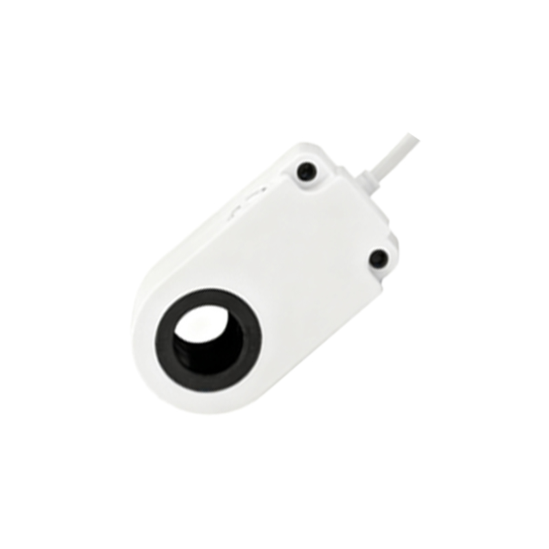
Essential Tools and Safety Precautions for Wiring
To wire a 4-wire proximity sensor safely and effectively, gather the necessary tools: a screwdriver, wire strippers, a multimeter for testing, and appropriate cables (often shielded to reduce electromagnetic interference). Always prioritize safety by disconnecting power from the control circuit before starting any wiring work. Verify that the voltage source matches the sensor's requirements, as incorrect voltage can lead to malfunction or permanent failure. Wear protective gear, such as insulated gloves and safety glasses, to prevent electrical shocks or injuries. Additionally, ensure the work area is dry and free from conductive materials that could cause short circuits. Following these precautions minimizes risks and promotes a secure installation process, which is vital in industrial environments where high voltages and heavy machinery are common.
Identifying and Connecting the Power Supply Wires
The first step in wiring involves connecting the power supply wires. A standard 4-wire proximity sensor has clearly labeled terminals: typically, brown (or red) for positive voltage (+V) and blue (or black) for negative voltage (0V or ground). Connect the brown wire to the positive terminal of your DC power supply, which should be within the sensor's specified range (e.g., 24V DC). Then, attach the blue wire to the negative terminal or ground of the power supply. Use secure connections, such as terminal blocks or crimp connectors, to prevent loose wires that could cause intermittent operation. After making these connections, double-check the polarity; reversing the wires can damage the sensor. Once powered, the sensor's indicator LED should light up, confirming that it is receiving electricity and is ready for output configuration.
Wiring the Output Signal Wires for Control Systems
The output signal wires handle the switching function of the sensor, transmitting a signal to a PLC, relay, or other control device when an object is detected. These wires are usually black (for output) and white (for output common or complementary signal), though colors may vary by manufacturer. For a PNP sensor, the black wire is the positive output; connect it to the input terminal of your control device, and link the white wire to the ground. In an NPN sensor, the black wire is the negative output; connect it to the input terminal, and the white wire to the positive supply. Ensure the load (e.g., a PLC input) is compatible with the sensor's output current and voltage. After wiring, test the sensor by bringing a metal target within its sensing range; the output should activate, and the control system should respond accordingly. This step verifies that the signal circuit is functioning correctly.
Testing and Troubleshooting Common Wiring Issues
After completing the wiring, conduct thorough testing to ensure optimal performance. Use a multimeter to measure the voltage at the sensor's power terminals, confirming it matches the supply voltage. Check the output signal by setting the multimeter to DC voltage mode and probing the output wires while activating the sensor; for a PNP type, the voltage should switch from low to high (e.g., 0V to 24V) upon detection. Common issues include no power due to loose connections, incorrect polarity, or a blown fuse. If the sensor fails to detect objects, verify the sensing distance and target material—some sensors only work with specific metals. Interference from nearby motors or cables can also cause erratic behavior; use shielded cables and proper grounding to mitigate this. Regular maintenance and periodic checks help sustain long-term reliability in industrial settings.
Best Practices for Installation and Maintenance
To maximize the lifespan and accuracy of your 4-wire proximity sensor, follow best practices