Understanding Photoelectric Sensors in Automation
Photoelectric sensors are indispensable components in modern industrial automation, providing non-contact detection of objects based on the modulation of light. They operate by emitting a beam of light, typically from an LED or laser diode, and detecting changes in the received light intensity caused by the presence, absence, or distance of a target object. These sensors excel in applications requiring high speed, long sensing ranges, and detection of a wide variety of materials, including glass, metal, plastic, and liquids. Their versatility makes them a preferred choice over proximity sensors for many tasks, especially where precise positioning or clear object differentiation is required. The core principle involves an emitter, a receiver, and the target. The disruption or reflection of the light beam triggers an electrical output signal, which is then used to control machinery, count items, or verify process steps.
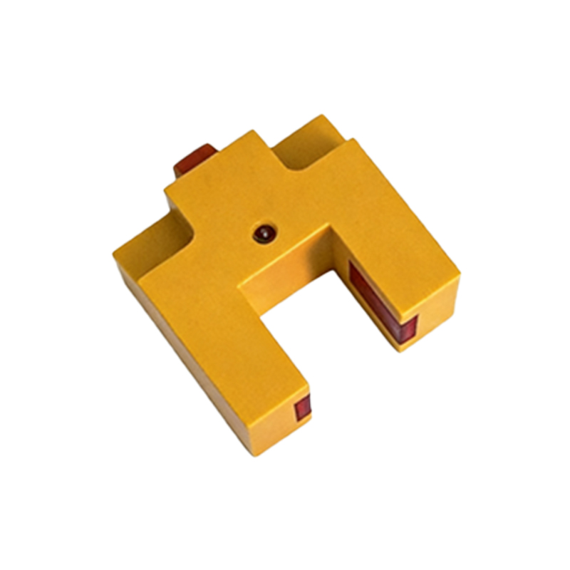
Key Control Configurations and Their Diagrams
Several standard control configurations define how photoelectric sensors are wired and function within a circuit. The first is the Diffuse (Proximity) Mode. In this setup, the emitter and receiver are housed in the same unit. The sensor detects light reflected directly from the target object. A common example image would show the sensor facing a conveyor belt, with its emitted light cone hitting a passing box and reflecting back to the receiver, triggering a switch. This mode is ideal for detecting objects at short to medium ranges without a separate reflector. The second is the Retro-reflective Mode. Here, the sensor unit contains both emitter and receiver, but it uses a separate reflector (corner-cube prism) placed opposite. The beam travels to the reflector and back. An object breaking this beam path is detected. Example imagery often depicts a sensor and reflector on either side of a doorway or conveyor, detecting break-in or break-out events with high reliability.
Through-Beam (Opposed) Mode for Maximum Reliability
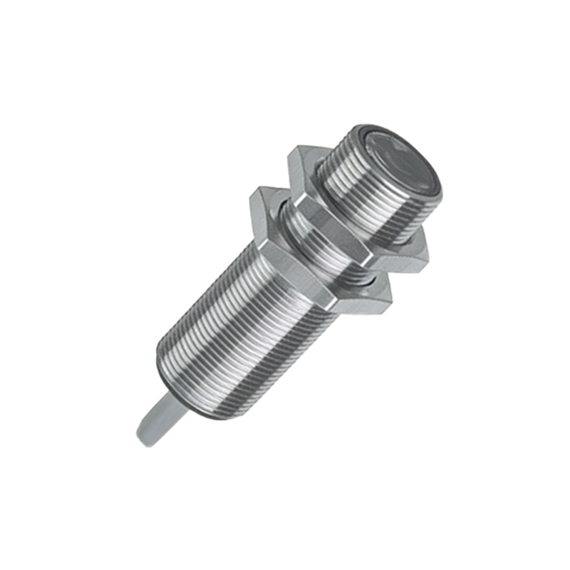
The Through-Beam (or Opposed) Mode offers the highest sensing reliability and longest range. The emitter and receiver are separate, opposing units. The emitter sends a continuous beam to the receiver. Any object that interrupts this beam is detected. Control example pictures for this mode are straightforward: one unit on each side of a production line, with the beam forming an invisible "curtain." This configuration is less susceptible to environmental factors like object color, reflectivity, or surface angle, making it perfect for precise counting, jam detection in high-speed bottling lines, or safety light curtains. The wiring diagram typically shows the emitter connected to a power supply and the receiver providing a switched output (PNP or NPN) to a Programmable Logic Controller (PLC) input module.
Application-Specific Control Examples with Visuals
Real-world control examples bring these configurations to life. Consider a Bottle Cap Presence Verification system on a filling line. A diffuse sensor is positioned above the conveyor. A control schematic would show the sensor's output wired to a PLC digital input. The PLC ladder logic program might be: IF Sensor_Input = ON THEN Allow_Filling_Valve; ELSE Trigger_Reject_Arm. An accompanying image would illustrate the sensor detecting the shiny cap, with a green LED on the sensor unit indicating detection. Another example is Pallet Height Detection in a Warehouse. A retro-reflective sensor mounted on a vertical mast scans upwards. As a pallet rises, it breaks the beam at a predetermined height. The sensor signal stops the lift mechanism. The control diagram highlights the sensor's output interfacing with the motor controller's stop circuit, ensuring safe and accurate positioning.
Integrating Sensor Outputs with PLC Logic
The true power of photoelectric sensors is realized when their discrete outputs are integrated into a PLC-based control system. A typical wiring example image shows a 3-wire DC PNP sensor: brown wire to +24V DC, blue wire to 0V DC, and black wire (output) to the PLC input terminal. The PLC scans this input. In the software, a simple contact instruction references this input address. For instance, a "Box at Packing Station" sensor (through-beam) triggers a timer in the PLC logic to activate a pusher arm after a 2-second delay, ensuring precise positioning before action. Clear visual documentation of these wiring schematics and ladder logic snippets is crucial for installation, troubleshooting, and maintenance by electrical technicians.
Factors Influencing Sensor Selection and Placement
Selecting the right sensor and positioning it correctly is critical for reliable control. Example images often highlight pitfalls and solutions. Key factors include: Sensing Range (through-beam offers the longest), Target Characteristics (a diffuse sensor must be chosen based on the color and texture of the object), Environmental Conditions (presence of dust, steam, or ambient light may require sensors with modulated light or specialized housings), and Response Time (for high-speed counting). A good application picture might compare a diffuse sensor failing to detect a transparent bottle versus a through-beam sensor succeeding. Another might show a sensor mounted with a bracket to avoid vibration, with wiring neatly routed in a cable duct to prevent damage.
Advanced Features: Background Suppression and Color Sensing
Modern photoelectric sensors incorporate advanced features for complex tasks. Background Suppression (BGS) sensors, a type of diffuse sensor, can detect an object at a precise distance while ignoring objects beyond a set point. A control example could involve picking a part from a bin; the sensor must only detect the topmost item, not the ones below. The diagram illustrates the adjustable sensing window. Color Recognition sensors differentiate objects based on color, not just light intensity. An application image might show sensors on a sorting line distinguishing between red and blue plastic components, with outputs directing them to different chutes via separate PLC inputs and actuator controls. These features expand the scope of automated quality control and material handling.
Conclusion: The Visual Language of Reliable Control
Photoelectric sensor control example images and diagrams form a universal visual language for engineers and technicians. They translate electrical schematics, physical layouts, and logical sequences into an immediately understandable format. From the basic through-beam interruption to complex background suppression for precision robotics, these visuals are essential for designing, commissioning, and maintaining efficient automated systems. Consistently applying clear labeling, accurate wiring representations, and context-rich application photos ensures that the control intent is communicated effectively, minimizing errors and downtime in industrial operations. Mastery of both the sensor technology and its graphical representation is key to successful automation implementation.