Introduction to Hall Effect Proximity Sensing
Hall effect proximity sensors are fundamental components in modern industrial automation, robotics, and automotive systems. They operate on the principle of the Hall effect, where a voltage difference—the Hall voltage—is generated across an electrical conductor when a magnetic field is applied perpendicular to the current flow. This non-contact sensing technology is prized for its robustness, long operational life, and immunity to environmental contaminants like dust, oil, and moisture. Unlike inductive sensors, they can detect both static and dynamic magnetic fields, making them versatile for position and speed sensing of permanent magnets. The core value proposition of these sensors lies in their reliability and precision, but achieving and maintaining high accuracy is a multifaceted engineering challenge influenced by numerous variables.
Defining Accuracy in Hall Effect Sensors
Accuracy in the context of Hall effect proximity sensors is not a single specification but a combination of performance parameters. It primarily refers to the consistency and repeatability of the switching point or analog output relative to the target's position. Key metrics include operating point (the distance at which the sensor switches on), release point (the distance at which it switches off), and the resulting hysteresis. For linear analog output sensors, accuracy encompasses linearity error, sensitivity, and offset voltage. High accuracy means minimal deviation from the ideal response curve across the specified temperature range, voltage supply variations, and over the product's lifetime. It is crucial to distinguish accuracy from resolution; a sensor may have fine resolution but poor accuracy if its output is consistently skewed.
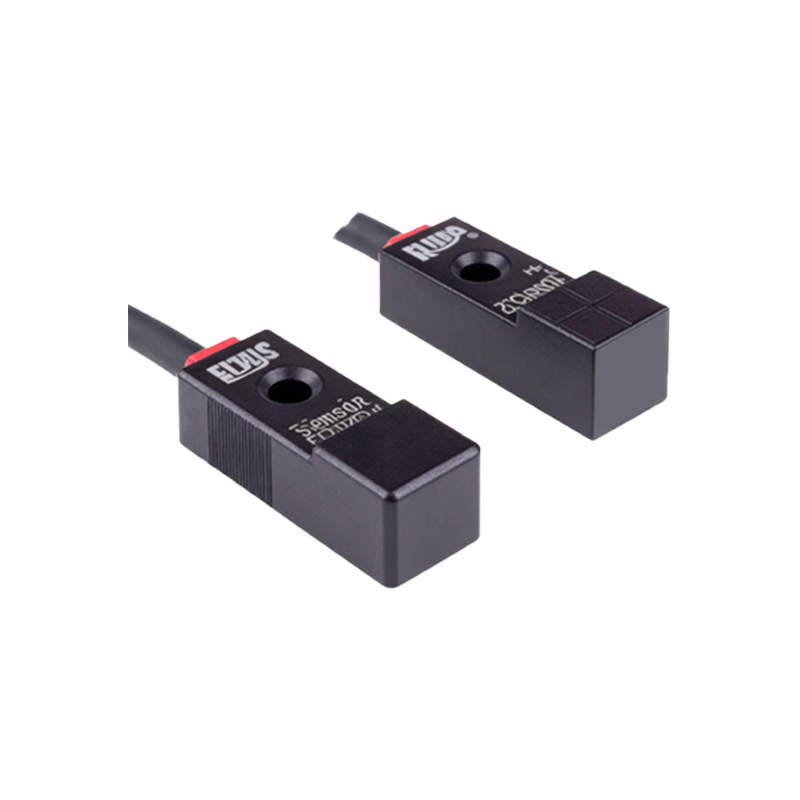
Primary Factors Influencing Sensor Accuracy
Several intrinsic and extrinsic factors directly impact the accuracy of a Hall effect proximity sensor. Magnetic field strength and gradient of the target magnet are paramount. A weak or inconsistent magnetic field leads to unreliable switching. The temperature coefficient of the Hall element itself is a critical intrinsic factor; the Hall voltage and offset voltage drift with temperature. Modern sensors integrate temperature compensation circuits to mitigate this. Supply voltage stability is another crucial factor, as variations can affect the internal reference voltages and amplifier gain. Mechanical alignment and the air gap between the sensor and the target must be precisely controlled in the system design. Finally, external magnetic interference from nearby motors or solenoids can induce significant measurement errors.
Electrical Noise and Signal Conditioning
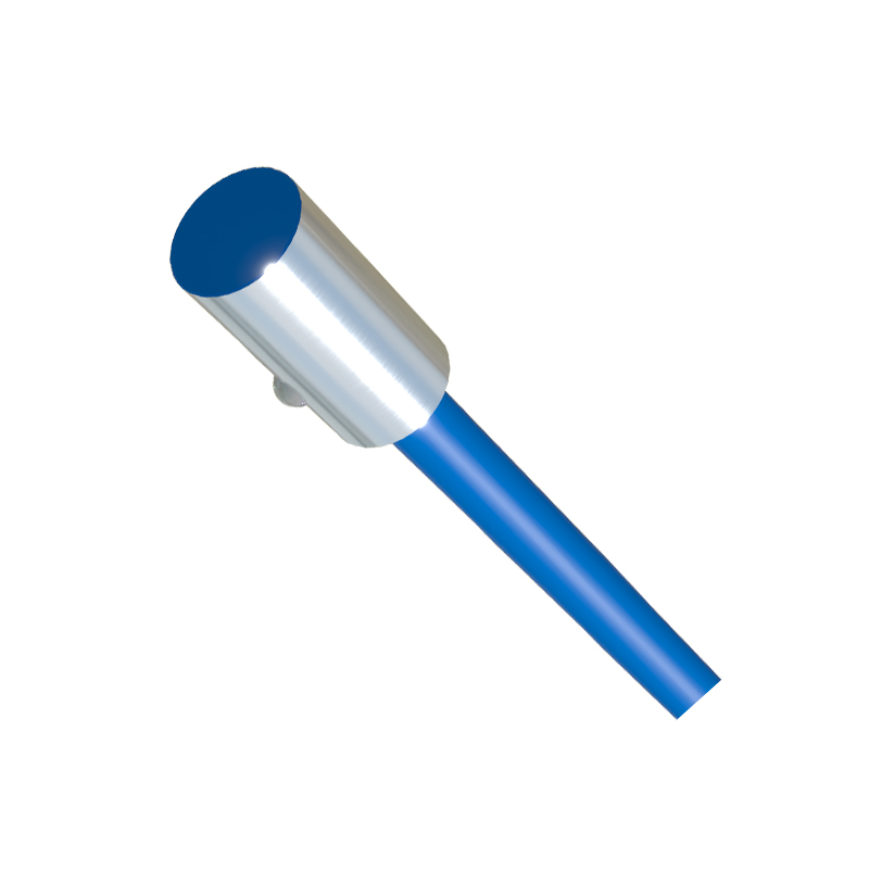
Electrical noise is a pervasive enemy of sensor accuracy. It can be introduced through the power supply lines, ground loops, or via electromagnetic interference (EMI) from adjacent high-power equipment. This noise can cause false triggering in digital switches or ripple in analog output signals. Effective signal conditioning is essential for high accuracy. This involves on-chip integration of low-noise amplifiers, Schmitt triggers for digital outputs with clean switching hysteresis, and filtering circuits. Shielding the sensor cable and employing twisted-pair wires are common installation best practices. For analog sensors, employing a dedicated analog-to-digital converter (ADC) with appropriate sampling rates and filtering in the controller can dramatically improve the signal-to-noise ratio and effective accuracy.
The Role of Sensor Calibration and Compensation
To achieve high accuracy, especially for precision analog or programmable sensors, calibration and compensation are indispensable. Factory calibration adjusts for initial offsets and sensitivity spreads inherent in semiconductor manufacturing. This is often stored in non-volatile memory on the sensor IC. Temperature compensation, often achieved through on-chip temperature sensors and correction algorithms, actively adjusts the output to counteract drift over the operational temperature range. Some advanced sensors offer end-user programmability, allowing for system-level calibration to account for specific magnet strengths or mechanical tolerances in the final assembly, thereby enhancing the overall system accuracy.
System Integration Considerations for Optimal Accuracy
Sensor accuracy can be compromised by poor system integration. The choice and placement of the target magnet are as important as the sensor itself. The magnet's size, material (e.g., neodymium, ferrite), polarization, and orientation must match the sensor's sensing direction. The mechanical fixture must ensure minimal variation in the air gap. For speed sensing applications using gear tooth or encoder ring targets, the tooth profile and pitch must be designed to provide a sharp enough magnetic flux variation. Power supply decoupling capacitors should be placed close to the sensor as recommended in the datasheet. Ensuring a stable, low-impedance ground connection prevents ground bounce and noise injection.
Advances in Technology Enhancing Accuracy
Recent technological advancements have pushed the boundaries of Hall effect sensor accuracy. The development of 3D Hall sensors, which can detect magnetic field components in multiple axes, allows for more precise angular position sensing and is less sensitive to alignment errors. Integrated microcontroller-based sensors with digital signal processing (DSP) capabilities can implement advanced filtering algorithms, linearization curves, and diagnostic functions. Innovations in packaging also contribute to accuracy by reducing stress on the Hall die