Introduction to Slot Type Photoelectric Sensors
A slot type photoelectric sensor, often termed a through-beam or fork sensor, is a fundamental component in industrial automation and control systems. Its primary function is to detect the presence, absence, or position of an object by utilizing a light emitter and a receiver housed in a single U-shaped body with a gap or "slot." When an object passes through this slot, it interrupts the light beam, triggering a change in the sensor's output state. This design offers significant advantages, including easy alignment and reliable detection, making it indispensable in applications like counting, edge detection, and safety interlocks. Understanding its representation in electrical diagrams is crucial for engineers and technicians to design, install, and troubleshoot control circuits effectively.
Deciphering the Core Schematic Symbol
The schematic symbol for a slot type photoelectric sensor is standardized under international norms such as IEC 60617. It is a composite symbol representing both the emitter and receiver. Typically, the emitter side is denoted by a diode symbol pointing outward, often accompanied by two parallel arrows indicating light emission. The receiver side is usually shown as a phototransistor or photodiode symbol—a circle with two diagonal arrows pointing inward. These two symbols are enclosed within a single dashed-line box or are placed in close proximity, graphically representing the integrated housing. The gap between the symbols visually implies the physical slot. Power supply connections (Vcc and GND) and the output signal line are clearly indicated, with the output often being a transistor (NPN or PNP) symbol to denote the switching nature.
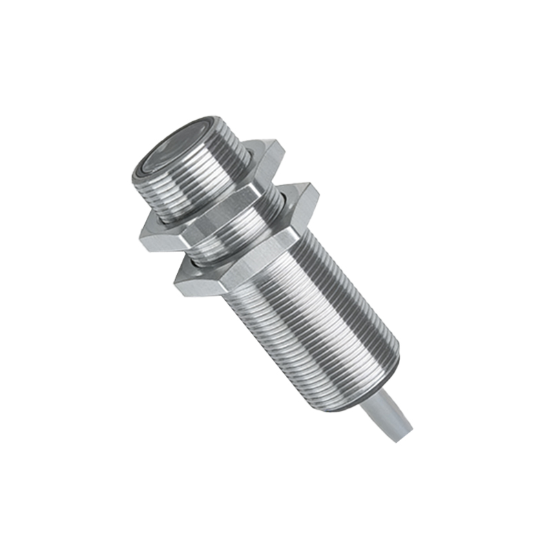
Variations in Symbol Representation
While the core concept remains consistent, schematic symbols can vary slightly based on the sensor's specific output configuration and manufacturer's documentation. A key variation involves the output transistor type. An NPN (sinking) output sensor will show the transistor symbol with the emitter arrow pointing outward from the base, while a PNP (sourcing) output will have the arrow pointing inward. Another variation indicates the light beam type; a constant beam is standard, but a modulated (pulsed) beam, used for immunity to ambient light, might be symbolized with a small wave icon near the emitter. Some detailed schematics also include symbols for built-in indicators (LEDs) or the timing logic functions (ON-delay, OFF-delay) if the sensor is of the programmable type. Always cross-reference the symbol with the specific sensor's datasheet.
Connection Diagrams and Practical Wiring
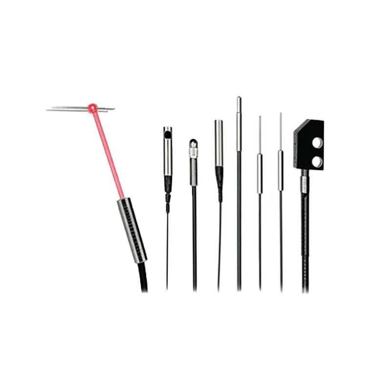
Beyond the abstract symbol, connection diagrams provide the practical wiring guide. A standard three-wire DC sensor schematic will show: Pin 1 (Brown wire) connected to the positive DC supply (+V), Pin 2 (Blue wire) connected to the negative DC supply (0V/GND), and Pin 3 (Black wire) as the switched output. The load (e.g., a PLC input, relay coil) is connected between the output wire and the opposite supply rail, depending on the NPN/PNP configuration. For an NPN sensor, the load connects between the output and +V; for a PNP, between the output and GND. The schematic clearly depicts this path, often showing the internal switching transistor and the photoelectric element. Understanding this diagram is essential to prevent incorrect wiring, which can lead to sensor damage or system malfunction.
Integration into Larger Control Systems
In a complete electrical schematic for a machine or process line, the slot sensor symbol is integrated with other components. It is typically shown in the control circuit section, not the power circuit. Its output is fed into a programmable logic controller (PLC) input module, a relay, or a counter. The schematic will trace the signal path from the sensor output, through any interposing devices, to the final controlling element like a motor starter or solenoid valve. The symbol's placement helps engineers visualize the logic: when the beam is interrupted (object present), the output switches, changing the state of the connected circuit. This integration highlights the sensor's role as a primary input device within the system's feedback loop.
Common Pitfalls and Troubleshooting Clues
Misinterpreting the schematic symbol can lead to common installation errors. Confusing NPN and PNP symbols is frequent, resulting in a non-functional circuit. Another issue is neglecting the required load resistor or incorrectly connecting it, especially when interfacing with PLCs. The schematic symbol does not always show external protective devices like surge suppressors, which might be necessary for long cable runs in electrically noisy environments. During troubleshooting, the schematic allows technicians to isolate the sensor circuit. By verifying voltage at the supply terminals and the expected state change at the output terminal relative to the beam condition, one can quickly determine if the fault lies with the sensor, the wiring, or the connected load.
Standards and Future Trends
Adherence to schematic symbol standards ensures universal comprehension across different industries and regions. The IEC 60617 and ANSI/IEEE Std 315 standards provide the foundation. As sensor technology evolves, so might symbolic representation. For instance, smart sensors with IO-Link communication capability may incorporate additional symbols near the output to denote a serial data line alongside the traditional switching output. However, the fundamental photoelectric symbol core will likely remain, preserving clarity and backward compatibility. For engineers, maintaining familiarity with these symbols and consulting the latest manufacturer schematics remains a best practice for accurate system design and documentation.