Introduction to M8 Right-Angle Proximity Sensors
M8 right-angle, or 90-degree, proximity sensors are a specialized variant of inductive sensors designed for space-constrained industrial environments. Characterized by their compact 8mm diameter threaded barrel and a sensing face oriented perpendicular to the mounting axis, these sensors solve critical installation challenges. Their primary function remains non-contact detection of metallic objects, typically ferrous and non-ferrous metals, but their unique form factor allows them to be mounted flush against machine frames, within tight cavities, or in areas where a straight-in sensor would physically interfere with the target or surrounding components. This design makes them indispensable in modern automated systems where real estate is at a premium and reliable detection is paramount.
Key Technical Specifications and Operating Principles
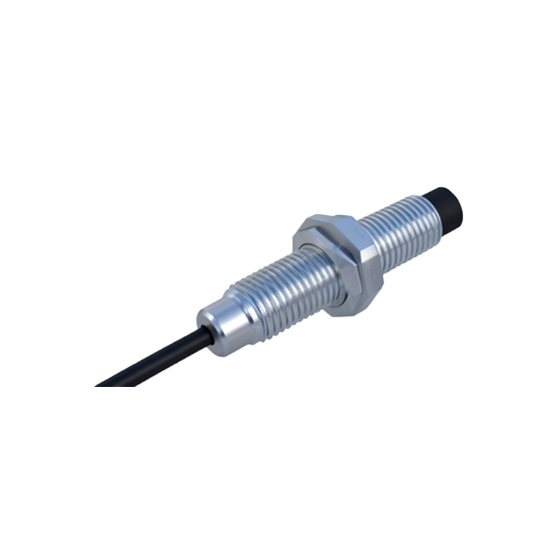
At their core, M8 right-angle sensors operate on the electromagnetic induction principle. An internal oscillator generates a high-frequency electromagnetic field emanating from the front face of the sensor. When a conductive metal target enters this field, eddy currents are induced on the target's surface. This causes a load on the oscillator, which is detected by the sensor's circuitry, triggering a solid-state output switch. Key specifications for these sensors include sensing distance, which for a standard M8 inductive sensor is typically up to 2mm, though this can vary with target material and sensor factor. They are commonly available in both PNP (sourcing) and NPN (sinking) output configurations, with 3-wire or 4-wire designs, the latter often incorporating both a normally open (NO) and normally closed (NC) signal. Operating voltage ranges are usually 10-30V DC, with protection ratings like IP67 or IP69K ensuring resilience against dust, coolants, and high-pressure washdowns.
Advantages of the Right-Angle Form Factor
The 90-degree bend offers several distinct mechanical and application advantages. First, it enables side-sensing, which protects the sensor's face from direct impact or accumulation of debris in applications like robotic grippers or linear slides. Second, it simplifies wiring management; the electrical connection (usually via a standard M8 connector) exits parallel to the mounting surface, allowing cables to be routed neatly along machine structures, reducing strain and improving organization. Third, it allows for installation where depth behind the mounting point is limited. A straight sensor might require significant rear clearance for its length, whereas a right-angle sensor's body runs parallel to the panel, consuming minimal depth. This is crucial in compact control cabinets, modular machinery, and gantry systems.
Common Industrial Applications and Use Cases
M8 right-angle proximity sensors find widespread use across automation sectors. In robotics, they are frequently employed as end-of-arm tooling sensors to detect the presence of a gripper jaw or a picked part. Within packaging machinery, they monitor the position of cams, detect missing caps on bottles, or verify the passage of items on conveyors where mounting space is lateral. CNC machine tools utilize them for tool presence detection in tight tool changers or for monitoring slide and door positions. Their robust construction also makes them suitable for harsh environments like welding cells (with weld-field immunity models) and food & beverage processing lines, where their sealed design withstands frequent cleaning.
Selection Criteria and Installation Best Practices
Selecting the correct M8 right-angle sensor requires careful consideration. The target material is primary; standard sensors work best with steel, while models with reduced sensing factors are needed for non-ferrous metals like aluminum or copper. The required sensing distance and any necessary safety margin should be calculated. Output type must match the PLC or controller input card (PNP vs. NPN). Environmental factors dictate the needed ingress protection (IP) rating and housing material, such as nickel-plated brass or stainless steel. During installation, ensure the sensor is mounted securely using its locknut, maintaining the specified blind zone around the sensing face. Avoid mounting multiple sensors directly opposite each other to prevent mutual interference. Always follow the manufacturer's wiring diagram to prevent damage, and consider using shielded cables in electrically noisy environments.
Maintenance and Troubleshooting Tips
While known for durability, these sensors require periodic checks. Routine maintenance involves inspecting the sensing face for buildup of metallic swarf, dirt, or paint, which can reduce effective sensing range. Verify the physical mounting for any loosening caused by vibration. Common troubleshooting steps include checking the power supply voltage at the sensor connector, verifying the output state with a multimeter or indicator, and ensuring the target is within the nominal sensing range and made of the correct material. A failure to switch may indicate sensor damage, wiring issues, or an incompatible target. Leveraging sensors with