Understanding Proximity Sensor Power Requirements
Before initiating any connection, it is paramount to understand the specific power requirements of your proximity sensor. Most industrial proximity sensors, including inductive, capacitive, and ultrasonic types, operate on Direct Current (DC) voltage. Common supply voltages are 10-30V DC or 10-65V DC, with 24V DC being the de facto standard in industrial control panels. Always consult the sensor's datasheet or nameplate for the exact voltage range (e.g., 12-24V DC) and current consumption. Mismatched voltage can lead to immediate failure, erratic operation, or reduced sensing range. For AC-powered sensors, typically less common, standard voltages like 90-250V AC may be specified. Ensuring the power supply's voltage regulation and current capacity (in amperes) meets or exceeds the total demand of all connected sensors is the foundational step for a reliable system.
Selecting the Appropriate Power Supply Unit
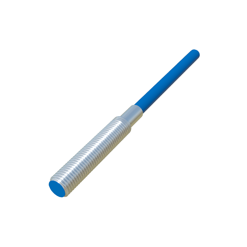
Choosing a suitable power supply is critical for stable sensor operation. A regulated switching power supply is recommended for its efficiency and stable output. Key selection criteria include output voltage matching your sensor's requirement (e.g., 24V DC), sufficient current rating, and appropriate safety certifications (e.g., UL, CE). Calculate the total current draw by summing the maximum current consumption of all sensors to be connected. Add a 20-30% safety margin to this total. For instance, if three sensors each draw 0.2A, the total is 0.6A; a 1A or higher power supply would be suitable. Consider using a dedicated power supply for sensors to avoid noise interference from other machinery, which can cause false triggering.
Wiring Connections and Polarity Considerations
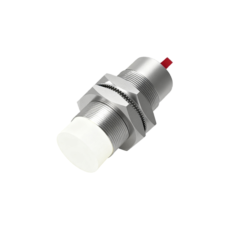
Correct wiring is non-negotiable. A standard 3-wire DC proximity sensor has brown (or red), blue, and black (or white) wires. The brown wire is for the positive supply voltage (+V), the blue wire is for the negative supply or common (0V), and the black wire is the switched output signal. Connect the brown wire to the positive terminal (+) of your DC power supply and the blue wire to the negative terminal (-). For 2-wire AC/DC sensors, wiring is in series with the load, and polarity is typically not a concern. Always ensure tight, secure connections using appropriate tools like ferrule crimps for stranded wire to prevent loose connections that lead to voltage drop, heat generation, and intermittent faults.
Implementing Proper Fusing and Circuit Protection
Circuit protection safeguards both the sensor and the power supply from overcurrent conditions such as short circuits. Install a fast-acting fuse or a circuit breaker in the positive supply line, close to the power source. The fuse rating should be slightly above the sensor's normal operating current but below the maximum current rating of the wiring. For example, for a sensor drawing 0.1A, a 0.25A or 0.5A fuse is appropriate. Additionally, in electrically noisy environments, consider adding a surge suppressor or a small-value capacitor across the power supply terminals to absorb voltage spikes. For long cable runs, protection against induced voltages is also advisable.
Grounding and Shielding for Noise Immunity
Industrial environments are rife with electromagnetic interference from motors, drives, and welding equipment. Proper grounding and shielding are essential for noise immunity. Always connect the shield/drain wire of a shielded cable to a clean earth ground at the power supply end only, avoiding a "ground loop." The metal housing of the sensor, if present, should also be grounded. Use twisted-pair cables for the supply wires to minimize magnetic interference. Keep sensor cables away from high-voltage power lines and separate them by at least several inches. A stable, low-impedance ground reference ensures the sensor's internal circuitry interprets signals correctly, preventing false outputs.
Verification and Troubleshooting Post-Connection
After completing the wiring, do not energize immediately. First, perform a visual inspection for correct polarity, secure connections, and no pinched wires. Use a multimeter in continuity mode to check for accidental shorts between wires. Once verified, power on the system. Use the multimeter in DC voltage mode to confirm the voltage at the sensor's terminals is within the specified range. Activate the sensor by bringing the target material within its sensing range. Observe the output indicator LED (if equipped) and measure the output signal voltage. If the sensor fails to operate, systematically check: power supply output, fuse integrity, wiring continuity, and ensure the target material and distance are appropriate for the sensor type.