Understanding Proximity Sensor Fundamentals
Proximity sensors are non-contact electronic devices designed to detect the presence or absence of an object within a defined sensing range without physical contact. Their operation hinges on various physical principles, primarily electromagnetic fields, light, or sound. The most common types include inductive sensors for detecting metallic objects, capacitive sensors for detecting both metallic and non-metallic materials, and photoelectric sensors using light beams. The core advantage lies in their reliability, high switching speed, and longevity, as the absence of mechanical contact eliminates wear and tear. Selecting the correct sensor begins with a clear understanding of the target object's material, size, required sensing distance, and the environmental conditions of the application, such as temperature, humidity, and potential contaminants.
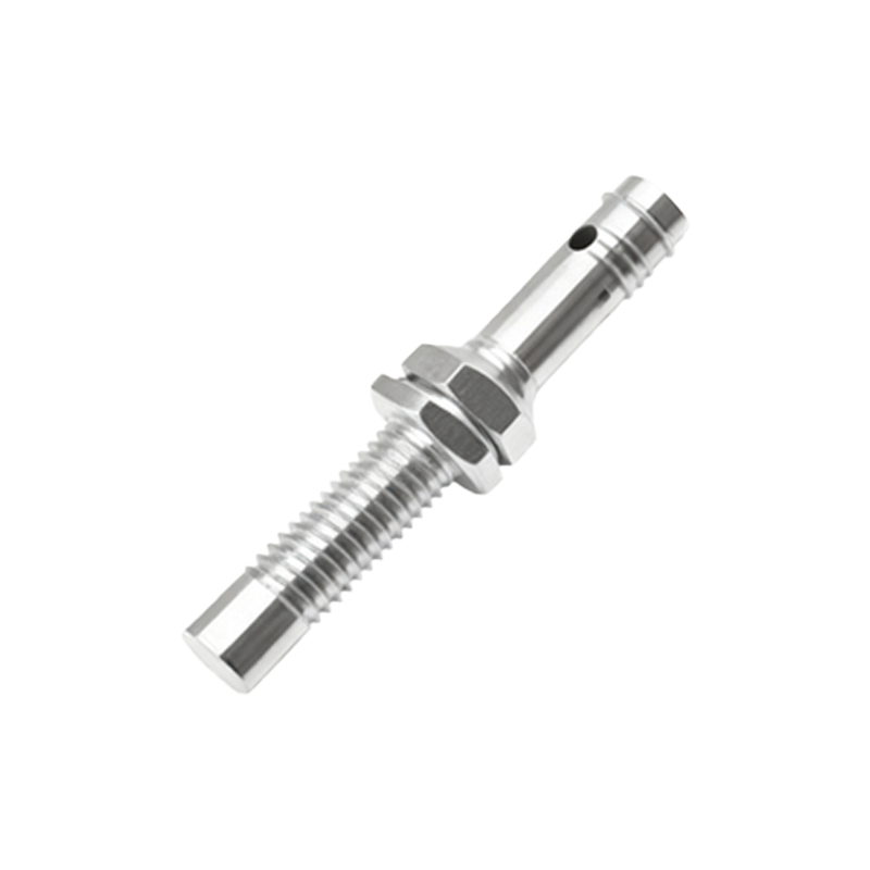
Key Installation and Mounting Considerations
Proper installation is critical for optimal sensor performance. First, ensure the sensor is mounted securely to prevent vibration-induced false triggers or damage. For inductive and capacitive sensors, maintain the specified lateral and axial sensing distances, considering the manufacturer's recommended reduction factors for different materials. The sensor face should be parallel to the target surface. Avoid mounting sensors in close proximity to each other to prevent mutual interference, a phenomenon known as "crosstalk." Typically, a minimum spacing of two to three times the sensor diameter is advised. For flush-mounted inductive sensors, they can be embedded in metal, while non-flush types require a clearance zone around the sensing face. Always refer to the datasheet for specific mounting requirements and environmental protection ratings like IP67 for dust and water resistance.
Electrical Wiring and Connection Procedures
Correct electrical integration is paramount. Most industrial proximity sensors operate on DC (10-30V DC) or AC voltages and come in three-wire configurations (PNP or NMP sourcing) or two-wire versions. For a standard three-wire DC sensor, connect the brown wire to the positive supply (+V), the blue wire to the common negative (0V), and the black wire is the switched output signal. It is essential to include a protective fuse in the circuit. Always ensure proper grounding and shielding, especially in environments with high electromagnetic noise. For long cable runs, use shielded cables and ground the shield at the controller end only to prevent ground loops. Connect the load (e.g., a PLC input, relay, or indicator lamp) between the output wire and the opposite supply rail, as per the sensor's sourcing type.
Configuration and Sensitivity Adjustment
Many proximity sensors feature a potentiometer or teach-in function for adjusting sensitivity or the sensing distance. This adjustment is crucial for fine-tuning the sensor to detect specific objects while ignoring background interference. For a capacitive sensor, adjust the sensitivity to detect a specific material without being triggered by a passing person or changes in humidity. For an inductive sensor, sensitivity adjustment can help discriminate between different grades of steel or aluminum. Use the manufacturer's recommended procedure: often involving placing the target object at the desired detection point and turning the potentiometer until the indicator LED activates. Avoid setting the sensitivity to its maximum, as this can make the sensor unstable and prone to false triggering from environmental noise.
Practical Application Examples in Automation
In automated systems, proximity sensors serve countless functions. A common application is object detection on conveyor belts for counting, sorting, or verifying part presence. Inductive sensors are ideal for detecting metal parts in robotic pick-and-place operations. Capacitive sensors can detect filled liquid levels in non-metallic tanks by sensing the change in capacitance when the liquid rises to the sensor's tip. In machine safety, they are used as part of interlock systems to confirm a guard door is closed before enabling machine operation. Another critical use is in rotary applications for speed monitoring or determining the angular position of a camshaft by detecting protruding metal teeth.
Troubleshooting Common Operational Issues
When a proximity sensor malfunctions, a systematic approach is needed. First, verify the power supply voltage with a multimeter. Check the indicator LED (if present); a constantly lit or unlit LED can indicate a wiring error, short circuit, or sensor failure. Ensure the target object is within the nominal sensing range and is of the correct material. For intermittent operation, investigate potential sources of electrical noise, loose connections, or a fluctuating power supply. Physical damage to the sensing face or cable can also cause failure. If sensitivity seems off, recalibrate according to the manual. Remember that excessive buildup of dirt, grease, or metal chips on the sensing face can drastically reduce the effective sensing distance and must be cleaned regularly.
Ensuring Long-Term Reliability and Maintenance
While proximity sensors are largely maintenance-free, proactive measures ensure long service life. Implement a regular inspection schedule to check for physical damage