Introduction to 4-Wire Proximity Sensors
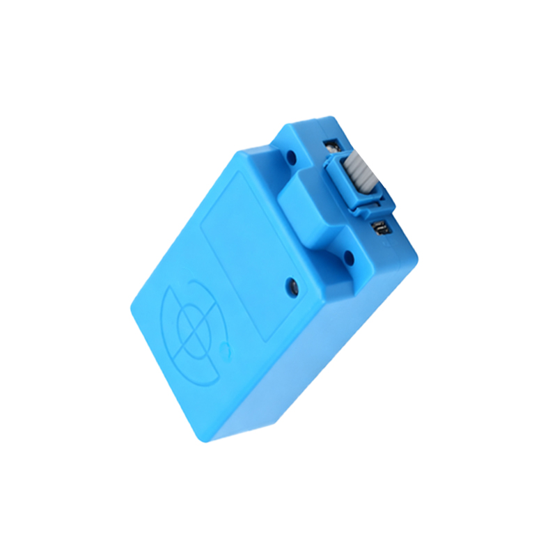
The 4-wire proximity switch sensor represents a fundamental and widely utilized configuration in industrial automation. Unlike its 2-wire or 3-wire counterparts, this design offers distinct advantages in terms of control flexibility and signal integrity. A standard 4-wire sensor typically comprises two wires dedicated to the power supply, usually labeled as brown (+V) and blue (0V or common), and two separate wires for the output signal. This separation of power and output circuits is the defining characteristic, allowing for more complex interfacing with programmable logic controllers (PLCs), relays, and other control systems. The output itself can be configured as either a normally open (NO) or normally closed (NC) contact, and it can be of a sourcing (PNP) or sinking (NPN) type, though the 4-wire design most commonly houses a relay or a solid-state switch with isolated contacts. This architecture provides a robust solution for applications requiring high electrical noise immunity and the ability to switch different load types or voltages independently of the sensor's internal logic supply.
Wiring Configuration and Color Code Standards
Adherence to international wiring color codes is critical for safe and correct installation. While variations can exist by manufacturer or region, the most prevalent standard for DC 4-wire proximity sensors follows this pattern: The brown wire is connected to the positive DC supply voltage (+V). The blue wire is connected to the DC common or ground (0V). These two wires power the sensor's internal oscillator and evaluation electronics. The remaining two wires, often black and white, are the switched output terminals. In a typical configuration, the black wire is the output common, and the white wire is the switched signal. When the sensor detects a target within its sensing range, the internal switch closes (or opens, depending on the logic), creating a connection between the black and white wires. It is paramount to consult the specific sensor's datasheet, as colors like gray, pink, or yellow may also be used, and the output type (e.g., NPN vs. PNP) will dictate the exact wiring to the load and power supply.
Operating Principles and Sensing Technologies
The core sensing technology within a 4-wire housing is identical to other proximity sensors, primarily inductive or capacitive. Inductive sensors, the most common for metal detection, generate an electromagnetic field from a coil driven by the internal oscillator. When a metallic target enters this field, eddy currents are induced, which dampen the oscillation amplitude. The sensor's circuit detects this change and triggers the output switch. Capacitive sensors operate on a similar principle but respond to a change in capacitance, allowing them to detect non-metallic materials like liquids, plastics, or wood. The 4-wire design does not alter the sensing principle but provides a superior platform for the output switching mechanism. The separation allows the sensing electronics to be optimized for sensitivity and stability, while the output stage can be designed to handle higher currents, different voltages (e.g., 120VAC), or provide galvanic isolation.
Key Advantages and Application Scenarios
The primary benefit of a 4-wire sensor is the complete electrical isolation between the power supply circuit and the output switching circuit. This isolation enhances reliability by preventing ground loops and minimizing the impact of electrical noise from heavy loads on the sensitive sensing circuitry. It allows the output to switch a load that operates at a completely different voltage than the sensor's supply. For instance, a sensor powered by 24VDC can reliably switch a 120VAC lamp or relay coil. This flexibility makes 4-wire sensors ideal for complex control panels, machine tools, material handling systems, and packaging machinery where multiple voltage domains coexist. They are also favored in safety-interlock circuits due to their clear separation of circuits, which can simplify diagnostics and comply with certain safety standards.
Installation, Troubleshooting, and Best Practices
Proper installation is crucial for optimal performance. Ensure the sensor is mounted securely, with the correct sensing distance and free from interference by adjacent metal structures. Always disconnect power before wiring. Use shielded cables in electrically noisy environments, connecting the shield to ground at one end only. For troubleshooting, a systematic approach is best. First, verify the power supply voltage across the brown and blue wires. If correct, use a non-metallic tool to simulate a target in front of the sensor's face. Next, check the output state with a multimeter. If the sensor is powered and a target is present, but the output does not change state, the sensor may be faulty. Also, verify the load connected to the output wires is within the sensor's specified current and voltage ratings