Introduction to the Integration
Connecting a photoelectric sensor to a Variable Frequency Drive (VFD) is a common requirement in modern industrial automation for precise speed control, positioning, and safety interlocks. A photoelectric sensor detects the presence, absence, or distance of an object using a light transmitter and receiver. When integrated with a VFD, it can provide real-time feedback to adjust motor speed, initiate processes, or trigger alarms. This setup enhances system responsiveness and efficiency in applications like conveyor systems, packaging machinery, and material handling. Understanding the correct wiring, parameter configuration, and potential challenges is crucial for a reliable and functional system. This guide outlines the step-by-step process and best practices for a successful integration.
Understanding Sensor and VFD Signal Types
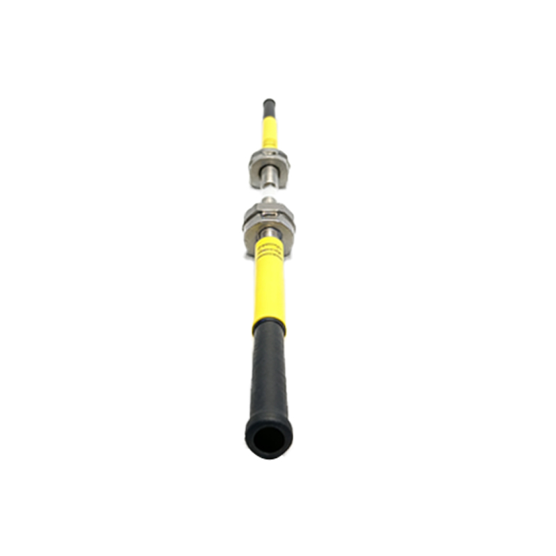
The first step is to identify the output signal type of the photoelectric sensor. Common outputs include NPN (sinking), PNP (sourcing), analog (0-10V or 4-20mA), and relay contact outputs. Similarly, the VFD must have compatible input terminals to accept these signals. Most VFDs are equipped with digital inputs for start/stop commands and analog inputs for speed reference. For basic on/off control, a digital sensor output can be connected to a VFD's digital input. For proportional speed control based on distance or object count, an analog sensor output is required. Always consult the datasheets of both the sensor and VFD to verify voltage levels, current ratings, and signal compatibility to prevent damage to the devices.
Wiring and Electrical Connections
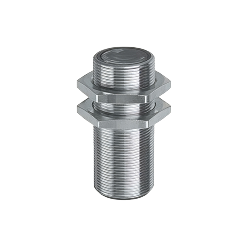
Proper wiring is critical for noise immunity and safe operation. For a typical NPN sensor connection to a VFD digital input: connect the sensor's brown wire (+V, usually 12-24V DC) to the VFD's auxiliary DC power supply positive terminal. Connect the sensor's blue wire (0V common) to the DC supply negative terminal. Connect the sensor's black wire (output signal) to the designated digital input terminal on the VFD. Ensure the VFD's common terminal for digital inputs is connected to the same DC negative. Use shielded cables for analog signals, grounding the shield at one end (typically the VFD side) to minimize electromagnetic interference from the motor power lines. Always disconnect power before making connections and follow local electrical codes.
Configuring VFD Parameters
After wiring, the VFD parameters must be programmed to recognize and respond to the sensor signal. Access the VFD's parameter menu using its keypad or software. For a digital input, assign the specific terminal function—for example, set it as "Run Enable," "Multi-speed Select," or "Fault Reset." For an analog input, set the parameter to define the input type (voltage or current) and scaling. For instance, map a 4-20mA sensor signal to correspond to 0-50 Hz motor speed. Adjust filter times to prevent false triggering from signal noise. Some advanced VFDs allow logic programming (like PLC functions) to create custom responses based on sensor input, enabling complex sequencing without an external controller.
Application Examples and Use Cases
In a conveyor system, a photoelectric sensor can detect package gaps. Its signal can tell the VFD to slow down or stop the motor for accumulation or sorting. In winding machines, an analog sensor measuring material diameter can provide feedback to the VFD to adjust tension by varying speed. For safety, a sensor guarding a hazardous zone can be wired to a VFD's fault input to immediately halt the motor if an object is detected. In automated storage, sensors count items and signal the VFD to index the motor to precise positions. These applications demonstrate how the integration adds intelligence, reducing manual intervention and improving throughput and safety.
Troubleshooting Common Issues
Common issues include no response, erratic operation, or electrical noise interference. If the sensor doesn't trigger the VFD, check power connections, sensor alignment, and output indicator lights. Verify the VFD input is correctly assigned and activated. For erratic behavior, inspect wiring for loose contacts or damaged cables. Electrical noise from the VFD's high-frequency switching can affect sensor signals; ensure proper grounding, use ferrite cores on cables, and separate signal wires from power lines by at least 20 cm. If using an analog signal, calibrate the sensor and VFD scaling. Consulting the error codes in the VFD manual can provide specific diagnostic clues.
Best Practices for System Optimization
To ensure long-term reliability, select sensors with environmental ratings (IP67 for dust/water resistance) suitable for the installation area. Use surge protectors on sensor lines in areas with voltage spikes. Regularly clean the sensor lens to maintain detection accuracy. Implement periodic testing of the sensor-VFD response as part of preventive maintenance. Document the wiring diagram and parameter settings for future reference. For critical applications, consider redundant sensors or connecting the sensor to both the VFD and a supervisory PLC for enhanced monitoring and control. Keeping firmware of the VFD updated can also provide improved functionality and compatibility.
Conclusion and Final Recommendations
Integrating a photoelectric sensor with a VFD is a straightforward process that significantly enhances automated system capabilities. Success hinges on correct component selection, meticulous wiring, and precise parameter configuration. Always prioritize safety by de-energizing equipment during installation. Start with simple on/off control before implementing complex analog feedback loops. As technology advances, many VFDs now offer built-in networking options, allowing sensor signals to be communicated digitally over protocols like Ethernet/IP or Modbus, simplifying wiring and enabling more advanced data integration. This integration remains a cornerstone of efficient, responsive, and intelligent motor control in modern industry.