Understanding Proximity Sensor Fundamentals
Proximity sensors are indispensable components in modern industrial automation, providing non-contact detection of metallic or non-metallic objects. These devices operate on various principles, including inductive, capacitive, ultrasonic, and photoelectric technologies. Inductive sensors detect ferrous metals through electromagnetic fields, while capacitive sensors respond to both metallic and non-metallic materials by sensing changes in capacitance. Understanding the specific type installed in your system is the first critical step toward effective inspection. Each sensor variant has unique operational parameters, sensing ranges, and environmental limitations that directly influence inspection protocols. Proper identification ensures that maintenance personnel apply correct testing procedures and interpret results accurately, preventing misdiagnosis of sensor health.
Pre-Inspection Safety and Preparation Procedures
Before initiating any inspection, comprehensive safety protocols must be observed. Always de-energize the equipment according to lockout-tagout (LOTO) procedures to prevent accidental activation. Verify zero energy state using appropriate voltage testers. Gather necessary tools including a digital multimeter, oscilloscope for signal analysis, target objects matching specifications, sensor datasheets, and cleaning supplies. Document the sensor's model number, serial number, and installation location. Review historical maintenance records for recurring issues. Environmental conditions should be assessed—check for excessive dust, moisture, temperature extremes, or electromagnetic interference that could affect sensor performance. Proper preparation minimizes downtime and ensures inspection accuracy.
Visual Inspection and Physical Assessment
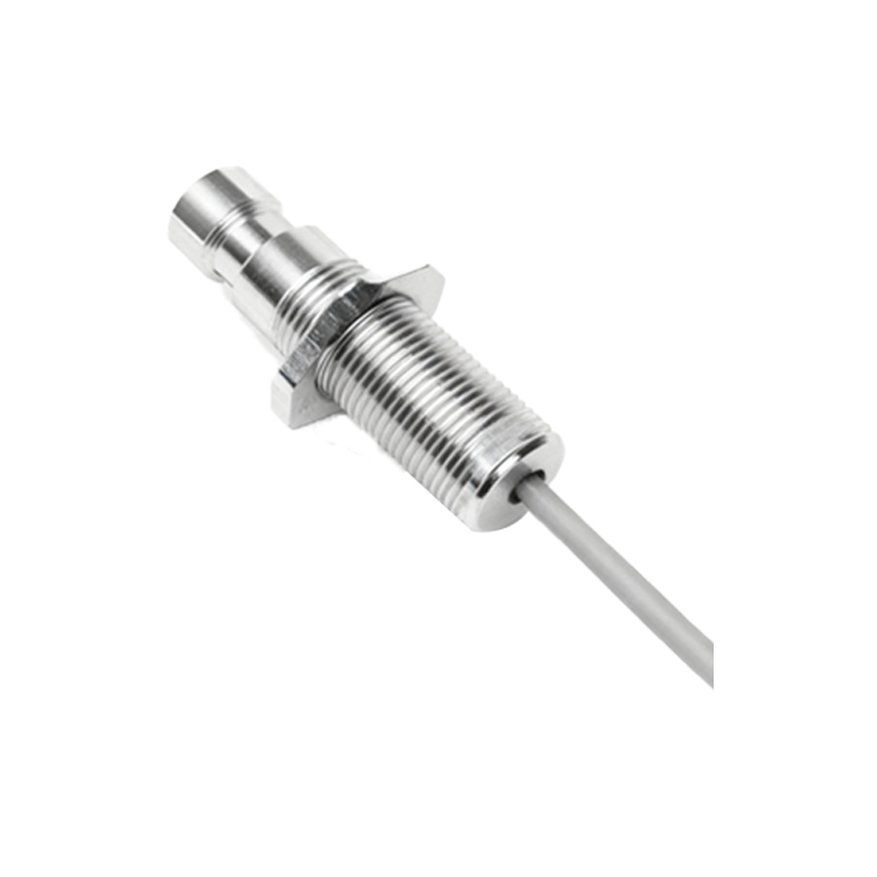
Conduct a thorough visual examination of the sensor assembly. Look for obvious physical damage such as cracks in the housing, bent or broken mounting brackets, or corrosion on electrical connections. Inspect cable integrity from the sensor body to the junction box, checking for cuts, abrasions, or pinch points that could compromise insulation. Verify that mounting hardware is secure and properly aligned according to manufacturer specifications. The sensing face must be clean and free from obstructions like paint buildup, metal chips, or oil accumulation. For cylindrical sensors, check thread condition; for rectangular sensors, inspect mounting surface flatness. Any physical compromise discovered during this stage typically requires immediate corrective action before proceeding with electrical tests.
Electrical Performance Verification
With power restored following safety protocols, measure the sensor's electrical characteristics. Use a multimeter to verify supply voltage matches rated specifications—typically 10-30V DC for most industrial sensors. Monitor current draw under load conditions; significant deviation from datasheet values indicates potential internal component failure. For switching outputs, measure voltage levels in both activated and deactivated states. PNP sensors should switch between supply voltage and zero, while NPN sensors switch between zero and negative supply. Test response time by rapidly moving a target in and out of sensing range while monitoring output with an oscilloscope. Compare measured switching frequency against manufacturer's maximum rating. Record all measurements for trend analysis and predictive maintenance planning.
Sensing Range and Repeatability Testing
Accurate detection distance is paramount for reliable operation. Using a certified test target of specified material and dimensions, gradually approach the sensor along its central axis. Mark the exact point where the output switches states—this is the actual sensing distance. Compare this measurement against the rated nominal range specified in technical documents. Most sensors operate reliably at 70-80% of nominal range to account for environmental variables. Next, perform repeatability tests by triggering the sensor 50-100 times from a fixed distance. Measure positional variation in switch points; excessive deviation indicates mechanical wear or electronic drift. For analog sensors, plot output signal versus distance to verify linearity across the entire operating range.
Environmental Interference Evaluation
Industrial environments present numerous challenges that can degrade sensor performance. Systematically evaluate potential interference sources. Electromagnetic interference from nearby motors, welders, or power lines may cause false triggering—use shielded cables and proper grounding if detected. Adjacent sensors operating at similar frequencies might interfere with each other; maintain minimum separation distances per installation guidelines. Temperature fluctuations affect electronic components and sensing distances; operate sensors within specified temperature ranges. Contaminants like cutting fluids, metal particles, or conductive dust can bridge sensing gaps or coat optical surfaces. Conduct tests under normal operating conditions to identify intermittent issues that might not appear during controlled inspections.
Diagnostic Troubleshooting Common Faults
When sensors malfunction, methodical troubleshooting identifies root causes efficiently. For complete failure, verify power supply integrity first, then check wiring continuity from sensor to controller. Intermittent operation often results from loose connections, vibration-induced wire fatigue, or marginal sensing distances. False triggers may stem from environmental interference, incorrect sensor type for application, or target material variations. Reduced sensing range frequently indicates aging electronic components, dirty sensing faces, or incorrect mounting. Always consult manufacturer