Introduction to Photoelectric Sensors
Photoelectric sensors are indispensable components in modern industrial automation, playing a critical role in object detection, positioning, and quality control. These sensors operate by emitting a light beam—typically infrared, visible red, or laser—and detecting changes in the received light signal caused by the presence or absence of a target object. The fundamental principle involves the interaction of light with objects, where the sensor's receiver analyzes reflected or transmitted light to determine object characteristics such as distance, size, or surface properties. Their versatility allows deployment across diverse environments, from clean rooms to harsh manufacturing floors, making them a cornerstone of Industry 4.0 and smart factory initiatives. Understanding their operational mechanics is the first step toward effective data acquisition.
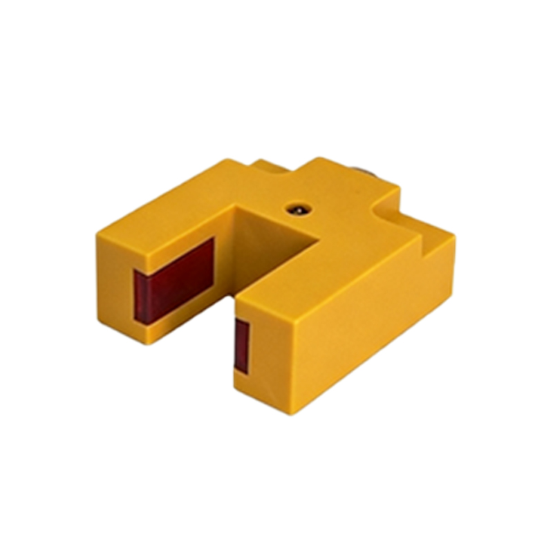
Key Parameters for Data Collection
Accurate data collection from photoelectric sensors hinges on monitoring specific operational parameters. The primary output is typically a digital signal (ON/OFF) indicating detection status, but analog variants provide continuous data proportional to distance or reflectivity. Critical parameters include response time, which defines the sensor's speed in reacting to changes; sensing range, specifying the maximum reliable detection distance; and environmental compensation values for temperature or contamination. Advanced sensors also provide diagnostic data such as signal strength, operating voltage, and internal temperature. For precise measurements, parameters like hysteresis (the difference between switch-on and switch-off points) and background suppression levels must be calibrated. System integrators must align these parameters with application requirements to ensure data integrity.
Wiring and Signal Conditioning
Proper electrical integration is fundamental to reliable data acquisition. Photoelectric sensors commonly utilize three-wire configurations (positive, negative, and signal) or two-wire loop-powered designs. Voltage outputs range from 10-30V DC for industrial controllers, while current loop outputs (4-20mA) are preferred for noise immunity in long-distance transmission. Signal conditioning involves converting raw sensor outputs into compatible formats for data acquisition systems. This may include amplification of weak signals, noise filtering using shielded cables and proper grounding, and isolation to prevent ground loops. For pulsed or modulated light sensors, demodulation circuits extract the relevant signal. Implementing surge protection and voltage regulation safeguards against electrical transients common in industrial settings.
Interfacing with Data Acquisition Systems
Bridging sensors with data acquisition (DAQ) systems requires appropriate interface hardware. Programmable Logic Controllers (PLCs) are the most common industrial interfaces, where sensor outputs connect to digital or analog input modules. For PC-based systems, industrial I/O cards or external DAQ modules convert signals to USB, Ethernet, or fieldbus protocols like PROFINET, EtherNet/IP, or IO-Link. IO-Link is increasingly significant as it enables bidirectional digital communication, allowing not only data collection but also parameter configuration and advanced diagnostics from a single port. Gateways and protocol converters facilitate integration with legacy systems. The choice of interface depends on required sampling rates, network architecture, and whether real-time processing or simple logging is needed.
Communication Protocols and Networks
Modern industrial networks streamline sensor data collection. Beyond basic I/O, sensors equipped with communication capabilities transmit data via standardized protocols. Common options include AS-Interface for simple binary sensors, Modbus RTU/TCP for serial and Ethernet networks, and PROFIBUS for more complex automation systems. Ethernet-based protocols like EtherCAT or Modbus TCP/IP support high-speed, deterministic data transfer essential for synchronized multi-sensor applications. Wireless protocols such as WirelessHART or Bluetooth Low Energy are emerging for mobile or hard-to-wire installations. Implementing these networks requires configuring node addresses, baud rates, and data frames to ensure seamless integration with supervisory control and data acquisition (SCADA) systems or manufacturing execution systems (MES).
Software Configuration and Data Logging
Software tools configure sensors and manage collected data. Manufacturer-specific configuration software, often accessible via USB or web interfaces, sets parameters like sensing mode (retro-reflective, through-beam, diffuse), light-on/dark-on operation, and timer functions. For data logging, SCADA software (e.g., Ignition, WinCC) or custom applications using Python, LabVIEW, or Clibraries read sensor values through OPC UA or MQTT servers. Structured query language (SQL) databases or time-series databases like InfluxDB store historical data for analysis. Key software considerations include setting appropriate sampling intervals to avoid aliasing, implementing data validation checks, and ensuring timestamp synchronization across the network for correlated multi-sensor analysis.
Data Analysis and Application Insights
Raw sensor data transforms into actionable insights through analysis. Basic applications count objects or verify presence, but advanced analysis detects trends. Statistical process control (SPC) uses detection timing data to monitor production line speed consistency. Machine learning algorithms can analyze reflectivity patterns to classify material types or identify surface defects. Vibration analysis from high-speed sampling can infer machine health. Integrating photoelectric sensor data with other sources (e.g., vision systems, encoders) in a data historian enables comprehensive digital twins of processes. The ultimate goal is predictive maintenance—where gradual changes in sensor response time or signal strength forecast component wear before failure occurs, minimizing downtime.
Calibration and Maintenance for Data Integrity
Maintaining data accuracy requires regular calibration and maintenance. Calibration involves verifying and adjusting the sensor's response against known reference targets at specified distances. Automated calibration routines are possible with smart sensors featuring teach-in functions. Maintenance tasks include cleaning lenses to prevent false triggers from dust or oil accumulation, checking alignment in through-beam setups, and verifying electrical connections. Environmental factors like ambient light interference, temperature drift, or mechanical vibration can degrade data quality; periodic audits identify such issues. Implementing a scheduled maintenance plan, supported by diagnostic data from the sensors themselves, ensures long-term reliability and trust in the collected data for critical decision-making.
Future Trends in Sensor Data Acquisition
The evolution of photoelectric sensor data acquisition is driven by digitalization and intelligence. The integration of edge computing allows sensors to perform initial data processing (like filtering or anomaly detection) locally before transmission, reducing network load. Enhanced IO-Link capabilities provide richer diagnostic data packets. The adoption of time-sensitive networking (TSN) over Ethernet enables precise, synchronized data collection from vast sensor arrays. Furthermore, the development of multispectral sensors that operate at multiple wavelengths can gather more complex material property data in a single unit. As Industrial Internet of Things (IIoT) platforms mature, seamless cloud integration will facilitate large-scale analytics across entire production facilities, pushing data collection from mere monitoring toward autonomous optimization.