Introduction to Pneumatic Proximity Sensing
Pneumatic proximity sensors, often referred to as air jet sensors, are critical components in industrial automation, particularly in environments where electrical interference, high temperatures, or explosive atmospheres pose risks. These sensors operate by detecting changes in air pressure or flow when an object interrupts a controlled air stream. Unlike their electronic counterparts, they rely solely on compressed air, making them inherently safe and durable. This case study delves into a practical application within a manufacturing assembly line, highlighting the design, implementation, and benefits of using pneumatic proximity sensors for object detection and positioning tasks.
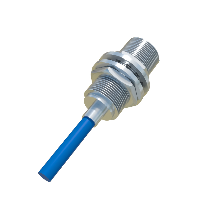
Working Principle and Design Features
The core mechanism involves a precision nozzle that emits a laminar flow of compressed air. When an object enters the sensing range, it disrupts this flow, causing a backpressure change that is measured by a diaphragm or pressure switch within the sensor. Key design features include adjustable sensitivity via air pressure regulation, typically operating at 1-10 bar, and a sensing distance ranging from a few millimeters to several centimeters. The sensor body is commonly constructed from stainless steel or brass to withstand harsh conditions like moisture, dust, and chemical exposure. This robust design ensures reliable performance without the need for complex electronics, reducing maintenance needs and lifecycle costs.
Application in Automotive Assembly Lines
In an automotive manufacturing plant, pneumatic proximity sensors are deployed to verify the presence of engine components on a conveyor belt. For instance, during cylinder head assembly, sensors are positioned to detect whether valve springs are correctly seated before robotic arms proceed with installation. The setup involves multiple sensors arranged in an array, each calibrated to specific tolerances to avoid false triggers from vibration or ambient air currents. By using compressed air from the plant's existing supply, integration is seamless, and the sensors provide real-time feedback to the pneumatic control system, halting the line if a misalignment is detected, thus preventing costly defects.
Advantages Over Electronic Sensors
Pneumatic sensors offer distinct advantages in certain scenarios. Their immunity to electromagnetic interference (EMI) makes them ideal for use near welding stations or high-power machinery. Additionally, they excel in explosive atmospheres, such as paint booths, where sparks from electronic devices could ignite fumes. With no electrical components, they also avoid issues related to heat generation or short circuits. Maintenance is straightforward, often limited to cleaning nozzles and checking air filters, which contrasts with the calibration and software updates required for electronic versions. This reliability translates to higher uptime and safety compliance in regulated industries.
Installation and Calibration Best Practices
Proper installation is crucial for optimal performance. Sensors should be mounted securely to minimize vibration effects, with air lines kept free of contaminants using filters and regulators. Calibration involves adjusting the air pressure to set the sensing threshold, often done via a manual knob or screw on the sensor body. In the case study, technicians used a test object of known dimensions to fine-tune the response, ensuring consistent detection across varying production speeds. Regular checks include monitoring air consumption and inspecting for leaks, as even minor pressure drops can affect accuracy. Documentation of settings aids in quick troubleshooting and replication across multiple production lines.
Performance Metrics and Real-World Outcomes
In the automotive application, the pneumatic sensors achieved a detection accuracy of 99.8% over a six-month period, with zero failures due to environmental factors. Response times averaged 10 milliseconds, sufficient for high-speed conveyor operations. Compared to previous inductive sensors, which experienced interference from nearby motors, the pneumatic system reduced false stops by 40%, boosting overall equipment effectiveness (OEE). Energy consumption was also lower, as the sensors utilized the plant's existing compressed air network without additional power draws. These outcomes underscore the sensor's efficiency in enhancing productivity while maintaining safety standards.
Future Trends and Innovations
Advancements in pneumatic technology are focusing on miniaturization and smart integration. Newer models incorporate micro-pneumatic circuits that allow for smaller form factors and increased sensitivity. Some systems now interface with digital controllers via pressure-to-electric converters, enabling data logging and predictive maintenance alerts. In the future, hybrid sensors combining pneumatic sensing with IoT connectivity could provide real-time analytics on air quality and component wear. As industries prioritize resilience and sustainability, the role of pneumatic proximity sensors is expected to expand, particularly in sectors like food processing and pharmaceuticals, where cleanliness and safety are paramount.
Conclusion and Industry Implications
This case study demonstrates that pneumatic proximity sensors remain a viable and often superior choice for specific industrial automation challenges. Their simplicity, durability, and safety features make them indispensable in demanding environments. Engineers should consider factors