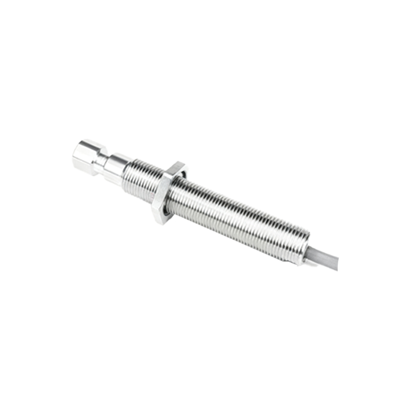
Wiring a proximity sensor correctly is essential for ensuring reliable operation in industrial automation, machinery safety systems, and various electronic applications. Whether you are a technician, engineer, or DIY enthusiast, understanding the proper connection methods can prevent malfunctions and enhance system longevity. This guide complements detailed video tutorials by explaining key steps and considerations for wiring common types of proximity sensors, including inductive, capacitive, and ultrasonic variants.
Proximity sensors detect the presence or absence of objects without physical contact, typically using electromagnetic fields or sound waves. They are widely used in manufacturing lines, robotics, and automotive systems. Before starting any wiring project, always prioritize safety: disconnect power supplies, use appropriate personal protective equipment, and refer to the sensor’s datasheet for specific voltage, current, and temperature ratings. Most sensors have three primary wires: brown (positive), blue (negative), and black (output). However, configurations may vary between PNP (sourcing) and NPN (sinking) models, as well between two-wire and four-wire designs.
Begin by identifying the sensor type and its wiring diagram. For a standard three-wire DC inductive proximity sensor, connect the brown wire to the positive terminal of your power supply (usually 10-30V DC). The blue wire links to the negative terminal or ground. The black wire is the output signal, which should be connected to the load, such as a programmable logic controller (PLC) input, relay, or indicator light. In PNP sensors, the output provides positive voltage when activated, while NPN sensors switch the ground connection. Ensure the load compatibility with the sensor’s output current—typically under 200mA—to avoid damage.
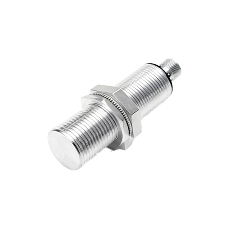
For two-wire AC sensors, wiring is simpler: one wire connects to the live AC source, and the other to the load. However, these sensors may have higher leakage currents, so using a bypass relay is often recommended for sensitive controls. Shielded cables are advisable in environments with electromagnetic interference to prevent false triggering. Additionally, maintain proper cable management by avoiding sharp bends and securing connections with crimp terminals or screw terminals to reduce vibration-related failures.
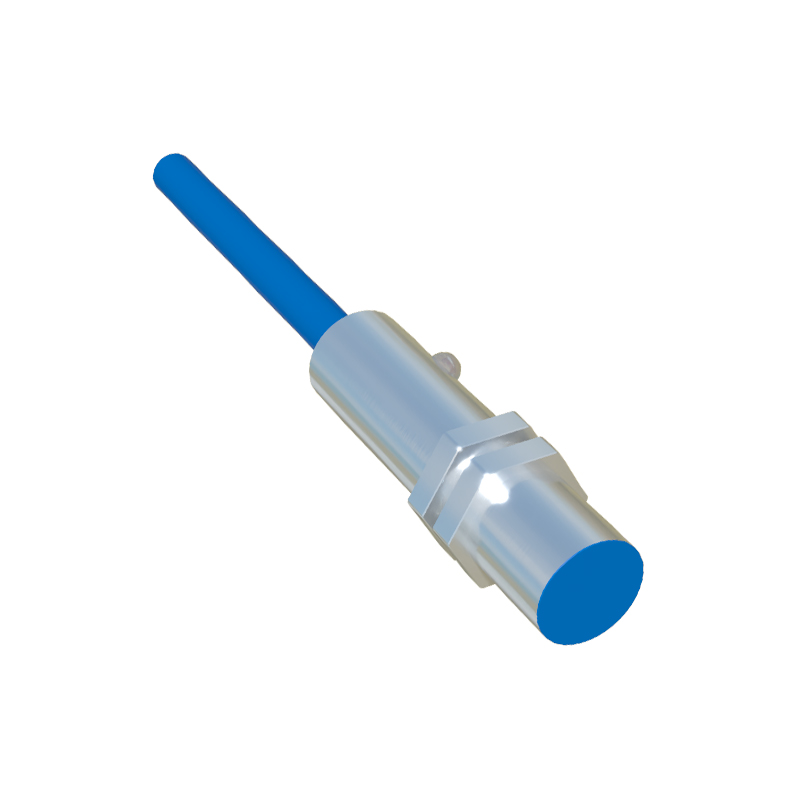
Testing is crucial after wiring. Restore power and observe the sensor’s indicator LED. Bring a target object within the specified sensing range; the LED should illuminate, and the output signal must trigger the connected device. If issues arise, double-check wiring against the diagram, verify power supply stability, and ensure the target material and size are suitable for the sensor’s specifications. For instance, inductive sensors work best with metals, while capacitive sensors can detect non-metallic materials.
Many online video resources demonstrate these steps visually, showing tools like multimeters for voltage checks and practical examples of sensor integration. Watching such videos can clarify complex points, such as wiring multiple sensors to a single PLC or implementing fail-safe circuits. Remember, practice in a controlled environment before deploying systems in critical applications. With correct wiring, proximity sensors offer years of maintenance-free service, boosting efficiency and safety in automated processes.